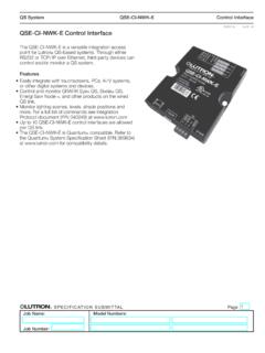
Transcription of QSE-CI-DMX Control Interface Spec (369372e)
1 SPECIFICATION SUBMITTALPageJob Name:Job Number:Model Numbers:QS SystemQSE-CI-DMXC ontrol Interfaces369372e 1 Control InterfaceDescriptionThe QSE-CI-DMX operates either in a standalone QS system or a Quantum system. It performs different functions depending on the system in which it is Standalone SystemThe QSE-CI-DMX Control Interface allows zones on a GRAFIK Eye QS to Control DMX512-controlled devices. Any zone on the GRAFIK Eye QS can be mapped to either a single DMX512 channel or to three separate DMX512 channels, for RGB / CMY color- Control SystemThe DMX channels (maximum of 32) are mapped to Quantum zones, and can be programmed as 1-channel lighting, 1-channel integration, or 3-channel RGB / CMY.
2 If the QSE-CI-DMX is part of a Quantum system, GRAFIK Eye QS zones cannot be programmed to Control DMX Map any zone on a GRAFIK Eye QS Control unit or any Quantum zone to any single DMX512 channel Map any zone on a GRAFIK Eye QS Control unit or any Quantum zone simultaneously to three DMX512 channels for RGB / CMY color- Control Integral RGB / CMY lookup table that maps GRAFIK Eye QS zone intensities or Quantum zone intensities to RGB /CMY values (colors) RGB / CMY table can be customized by using the Lutron QS Color Configuration Tool (PC application available on the CD packaged with the QSE-CI-DMX , and at ), or within the Quantum Q-Design softwareSPECIFICATION SUBMITTALPageJob Name:Job Number:Model Numbers:QS SystemQSE-CI-DMXC ontrol Interfaces369372e 2 Approvals RoHS CompliantPower Requirements Low-voltage SELV / PELV / NEC Class 2 Operating Voltage: 24 36 V- 65 mAEnvironment 32 F to 104 F (0 C to 40 C).
3 Relative humidity less than 90% non-condensing. Unit generates heat, maximum 8 BTU / Capabilities/LimitsQS Link System Limits (for units controlled by a GRAFIK Eye QS Control unit) 100 QS devices per QS link. 100 zones per QS Link System Limits (for units controlled by a Quantum system) 99 QS devices per QS link. 512 switch legs per link (each DMX channel = 1 switch leg). 32 DMX channels per QSE-CI-DMX Control Link Wiring Limits Total length of link must not exceed 2000 ft (610 m). Do not allow SELV / PELV / NEC Class 2 wires to contact line/mains Link System Limits Consult your DMX equipment Link Wiring Limits Each terminal can accept up to two 18 AWG ( mm2) wires.
4 Link must be 1000 ft (305 m) or less. DMX Link must begin and end with link terminators (available from Lutron; part number LT-1). Three pins on the DMX connector for connecting the QSE-CI-DMX to DMX512-controlled In a Quantum system, only 32 DMX channels can be programmed per device. The 32 channels can be any of the 512 available addresses, so DMX combiners can be used if more than 32 DMX channels need to be controlled from a single DMX universe. Daylighting is not supported for DMX loads. Loadshedding is not supported for DMX loads. Nightlighting is not supported for DMX loads. 1-channel lighting can be raised / lowered, but 1-channel integration and RGB can not.
5 Note: In a stand-alone system, raise / lower cycles through the RGB color table. RequirementsThe QSE-CI-DMX requires the following: At least one GRAFIK Eye QS Control unit connected to the QSE-CI-DMX through the QS communication link, or A Quantum system QS Link power supply; either: - GRAFIK Eye QS Control unit, as long as the GRAFIK Eye QS Control unit is NOT powering any other QS link devices drawing a total of two (2) or more power draw units - QS Link power supply, such as the QSPS-P1-1-50 or A Quantum Light Management Hub Note: The QSE-CI-DMX consumes 2 power draw units on the QS link.
6 See the SELV / PELV / NEC Class 2 QS Link Requirements and Wiring section for more information DMX512 link terminators at both ends of the DMX512 link (available from Lutron, part number LT-1) QS Communication Link Wire (SELV / PELV / NEC Class 2). See the Wire Sizes SUBMITTALPageJob Name:Job Number:Model Numbers:QS SystemQSE-CI-DMXC ontrol Interfaces369372e 3 ApplicationThe QSE-CI-DMX can be programmed so that any or all zones on a GRAFIK Eye QS Control unit can Control either 3 channels ( , RGB) or 1 channel ( , intensity of a single light). Raising or lowering a zone will change the color (for a 3-channel zone) or the intensity (for a 1-channel zone).
7 If, for example, you have an RGB LED fixture and a single stage light, you can configure your settings so that: Channels 3, 4, and 5 correspond to the red, green, and blue channels on the RGB LED fixture Channel 7 corresponds to the stage lightYou can then set up the GRAFIK Eye QS Control unit so that: Zone 3 s intensity = desired RGB fixture color Zone 6 s intensity = desired stage light intensityWhen you select a pre-programmed scene on the GRAFIK Eye QS Control unit: The QSE-CI-DMX converts the zone intensities for that scene into DMX512 channel settings. The RGB LED fixture will go to the color programmed for that scene, and the stage light will go to the desired Eye QS Control unitQSE-CI-DMXSELV / PELV / NEC Class 2 QS link wiring for system communicationDMX outputSPECIFICATION SUBMITTALPageJob Name:Job Number:Model Numbers.
8 QS SystemQSE-CI-DMXC ontrol Interfaces369372e 4 are in inches (mm) (63) (95) (108) (134) (27)Mounting holesTerminal blocks on this sideLEDs and addressing switches on this (9) (5) (5) (6)#6 or #8 (M3 or M4) screw recommendedMounting Hole DetailMounting OptionsMounting Methods Mount where terminal blocks, switches, and LEDs are accessible. Strip 3/8 in (10 mm) of insulation from wires. Each data link terminal will accept up to two 18 AWG ( mm2) wires. Connect wiring as shown on the Wiring page. LED 1 is continuously lit (Power) and LED 7 blinks rapidly (Data Link RX) when the SELV / PELV / NEC Class 2 Data Link is installed correctly.
9 Choose from the following mounting methods:1. Direct Wall Mounting Mount the Control Interface directly on a wall, as shown in Mounting Methods at right, using screws (not included). When mounting, provide sufficient space for connecting Rack Mounting Place the unit in the LUT-19AV-1U AV rack using screws provided with the unit. The LUT-19AV-1U will hold up to four Enclosed Wall Mounting If conduit is desired for wiring, use the LUT-5x10-ENC to mount one InterfaceWall13 SPECIFICATION SUBMITTALPageJob Name:Job Number:Model Numbers:QS SystemQSE-CI-DMXC ontrol Interfaces369372e 5 / PELV / NEC Class 2 QS Link Requirements and Wiring System communication uses SELV / PELV / NEC Class 2 wiring.
10 Wiring can be daisy-chained or T-tapped (see below). Wiring must be run separately from line / mains voltage. Total length of Control link must not exceed 2000 ft (610 m). Connect the terminal 1, 3, and 4 connections to all Control units, wallstations, and Control interfaces. See Powering the QSE-CI-DMX for pin 2 connectivity. The QSE-CI-DMX consumes 2 Power Draw Units (PDUs) on the QS link. For more information, see Power Draw Units on the QS Link, PN 369405, at Wiring ExampleT-Tap Wiring ExampleLUTRONLUTRONLUTRONLUTRONLUTRONLUT RONLUTRONGRAFIK Eye QS Control unitseeTouch QS wallstationsQSE-CI-DMXS ivoia QS power panelLUTRONLUTRONLUTRONLUTRONLUTRONLUTRO NLUTRONGRAFIK Eye QS Control unitseeTouch QS wallstationsQSE-CI-DMX (powered separately)QSPS power supplySivoia QS power panelSivoia QS shadeWire Sizes (check compatibility in your area)QS Link Wiring LengthWire GaugeLutron Cable Part NumberLess than 500 ft (153 m)Power (terminals 1 and 2)1 pair 18 AWG ( mm2)