Transcription of QSE-CI-NWK-E Control Interface - Lutron Electronics
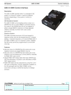
1 RSPECIFICATION SUBMITTALPageJob Name:Job Number:Model Numbers:QS SystemQSE-CI-NWK-EControl Interface369373e 1 Control InterfaceThe QSE-CI-NWK-E is a versatile integration access point for Lutron QS-based systems. Through either RS232 or TCP / IP over Ethernet, third-party devices can Control and/or monitor a QS Easily integrate with touchscreens, PCs, A / V systems, or other digital systems and devices. Control and monitor GRAFIK Eye QS, Sivoia QS, Energi Savr NodeTM, and other products on the wired QS link. Monitor lighting scenes, levels, shade positions and more. For a full list of commands see Integration Protocol document (P/N 040249) at Up to 10 QSE-CI-NWK-E Control interfaces are allowed per QS link. The QSE-CI-NWK-E is Quantum compatible. Refer to the Quantum System Specification Sheet (P/N 369634) at for compatibility SUBMITTALPageJob Name:Job Number:Model Numbers:QS SystemQSE-CI-NWK-EControl Interface369373e 2 SELV / PELV / NEC Class 2 Operating voltage: 24 36 V- 65 mAQS Link Limits The QS wired communications link is limited to 100 devices and 100 zones.
2 Each QSE-CI-NWK-E Control Interface counts as 1 device and 0 zones. Each QSE-CI-NWK-E Control Interface consumes 2 Power Draw Units (PDU) on the QS link. Refer to the QS Link Power Draw Units Specification Submittal (P/N 369405) at for more information. The maximum wiring length for the QS link is 2000 ft (610 m).Environment 32 F to 104 F (0 C to 40 C). Relative humidity less than 90% non-condensing. Indoor use only. Unit generates heat, maximum 8 BTU / Features Monitoring: Current scene, zone level, button presses, shade group levels. Control : Scene selection, scene lockout, zone lockout, sequencing, zone raise / lower, master raise / lower, set shade group level, simulate button the full list of features and commands, please refer to the Integration Protocol document (P/N 040249) on the accompanying CD or at Components Compatible with most QS devices. For a complete list of compatible components see Integration Protocol document (P/N 040249) at QS Link Power Supply, such as a: GRAFIK Eye QS.
3 QS Link power supply, such as the QSPS-P1-1-50 . Energi Savr NodeTM QS. QS Communication Link - SELV / PELV / NEC Class 2 (see QS Link Wire Sizes table).Protocol Integration Protocol document (P/N 040249) included on a CD accompanying the packaged QSE-CI-NWK-E . Also available for download, see Integration Protocol document (P/N 040249) at Connection Standard 9-pin female serial connector on Interface . 50 ft (15 m) maximum serial cable length. Dip switches are set at factory, all Off. Dip switches are used to set RS232 baud rate:DIP Switch Settings for RS232 Baud Rate115200 (default)38400192009600 Ethernet Connection Standard CAT5 (or better) cable, 328 ft (100 m) maximum, connects the QSE-CI-NWK-E Interface to a PC or other Ethernet source. Supports MDI / MDIX auto-crossover (no crossover cable needed). Auto-negotiation of 10 or 100 Mbps speed and full- or half-duplex operation. Default IP address is Can be changed using the Lutron DeviceIP tool located on the accompanying : Either the RS232 or the Ethernet can be used, but not 2 3 4 5 6 7 81 2 3 4 5 6 7 81 2 3 4 5 6 7 81 2 3 4 5 6 7 8 RSPECIFICATION SUBMITTALPageJob Name:Job Number:Model Numbers:QS SystemQSE-CI-NWK-EControl Interface369373e 3 are in inches (mm) (63) (95) (108) (134) (27)Mounting holesTerminal blocks on this sideLEDs and addressing switches on this (9) (5) (5) (6)#6 or #8 (M3 or M4) screw recommendedMounting Hole DetailMounting OptionsMounting MethodsLUT-19AV-1U2 LUT-5x10-ENCC ontrol InterfaceWall13 Mount where terminal blocks, switches, and LEDs are accessible.
4 Strip 3/8 in (10 mm) of insulation from wires. Each data link terminal will accept up to two 18 AWG ( mm2) wires. Connect wiring as shown on the Wiring page. LED 1 lights continuously (Power) and LED 7 blinks rapidly (Data Link RX) when the SELV / PELV / NEC Class 2 Data Link is installed correctly. Choose from the following mounting methods:1 Direct Wall Mounting Mount the Control Interface directly on a wall, as shown in Mounting Methods at right, using screws (not included). When mounting, provide sufficient space for connecting Rack Mounting Place the unit in the LUT-19AV-1U AV rack using screws provided with the unit. The LUT-19AV-1U will hold up to four Enclosed Wall Mounting If conduit is desired for wiring, use the LUT-5x10-ENC to mount one SUBMITTALPageJob Name:Job Number:Model Numbers:QS SystemQSE-CI-NWK-EControl Interface369373e 4 r m i n a l L o c a t i o n sLED and DIP Switch LocationsEthernet Link (to PC or AV EquipmentFemale 9-pin RS232 Link (to PC or AV Equipment)QS Link to other wired QS system DevicesDIP SwitchesLED 1: PowerLED 2: Ethernet ActivityLED 3: UnusedLED 4: RS232 Link TxLED 5: RS232 Link RxLED 6: QS Link TxLED 7: QS Link Rx1 2 3 4 5 6 7 RSPECIFICATION SUBMITTALPageJob Name:Job Number:Model Numbers:QS SystemQSE-CI-NWK-EControl Interface369373e 5 Link Standard 9-pin serial connector plugs into RS232 equipment, and to QSE-CI-NWK-E .)
5 Must be 50 ft (15 m) or SignalsSignalsPin on 9-Pin CableCom5 TxD3 RxD2123412 ABC123456LN4321To additional QS devicesRS232 Cable50 ft (15 m) Link: CAT5 Cable: 328 ft (100 m) Link To PC or AV EquipmentRear View of GRAFIK Eye QS Control Unit QS Link:1: Common2: V+3: MUX4: MUXSee next not connect Pin 2 if using external power LinkEthernet Link Wiring Standard CAT5 cable connects QSE-CI-NWK-E Interface to PC, router, or other Ethernet source. No crossover cable needed. Must be 328 ft (100 m) or less. Ethernet network and cable provided by SUBMITTALPageJob Name:Job Number:Model Numbers:QS SystemQSE-CI-NWK-EControl Interface369373e 6 Wiring (continued): QS Link Wiring Methods (choose one)Powered by GRAFIK Eye QS Control UnitPowered by a QS Link Power Supply*123412 ABC123456LN4321To additional wallstations/ Control interfacesTo additional wallstations/ Control interfacesRear View of GRAFIK Eye QS Control Unit PDU supplying device GRAFIK Eye QS Control Unit shown QS LinkQS LinkQS Link1: Common2: V+3: MUX4: MUXData Link:4: MUX3: MUXSee QS Link Wire Sizes tableSELV / PELV / NEC Class 2 Power wiring: 2: V+ 1: CommonSee QS Link Wire Sizes table System communication uses SELV / PELV / NEC Class 2 wiring.
6 Follow all local and national electrical codes for installation. Each terminal accepts up to two 18 AWG ( mm ) wires or one 12 AWG ( mm ) wire. Total length of Control link must not exceed 2000 ft (610 m). Do not allow SELV / PELV / NEC Class 2 wires to contact live / mains wire. Typical Wire Sizes: See QS Link Wire Sizes table. Connect the terminal 1, 3, and 4 connections to all Control units, wallstations, and Control interfaces in the QS system. For terminal 2 connectivity, see Cable See QS Link Wire Sizes tableQS Power Supply*(1) 18 AWG ( mm2) Common(1) twisted pair22 AWG( mm2)QS Link Wire Sizes (check compatibility in your area)QS Link Wiring LengthWire GaugeLutron Cable Part Number< 500 ft (153 m)Power (terminals 1 and 2)1 pair 18 AWG ( mm2)GRX-CBL-346S (non-plenum)GRX-PCBL-346S (plenum)Data (terminals 3 and 4)1 twisted, shielded pair 22 AWG ( mm2)500 ft 2000 ft(153 m 610 m)Power (terminals 1 and 2)1 pair 12 AWG ( mm2)GRX-CBL-46L (non-plenum)GRX-PCBL-46L (plenum)Data (terminals 3 and 4)1 twisted, shielded pair 22 AWG ( mm2)Do not use external power supply if connecting Pin 2Do not use external power supply if connecting Pin 2* Note: For details regarding powering from the QS Link, please refer to the QS Power Draw Units Specification Submittal (P/N 369405) at