Transcription of Reactor Calculation using Simulation Software
1 1 Reactor Calculation using Simulation Software (Revised from Senior Project Report by Ryan P. Thibault 2001-02) The PRO/II process Simulation program performs rigorous mass and energy balances for a range of chemical processes from oil/gas separation to reactive distillation. The graphical user interface, Provision, provides a fully interactive, Windows based environment for the user. Many industries, such as Refining, Petrochemicals, and Polymers, can take advantage of PRO/II s usefulness.
2 PRO/II also has many different applications. The user can design new processes, troubleshoot existing processes, evaluate alternate plant configurations, or optimize plant yield and efficiency to list a few. The easy to use interface of Provision incorporates point-and-click and drag-and-drop functionality for defining streams and unit operations. This makes drawing Process Flow Diagrams (PFD s) very simple. Provision also incorporates many Microsoft standards, such as OLE Automation, enabling the user to quickly transfer graphics and process data to other Windows applications.
3 It also allows you to configure the Simulation environment to suit your preferences in areas such as units of measure and thermodynamics. PRO/II s interactive color-coded data entry and validation system guides you through Simulation setup and execution. Along with PRO/II s ease of use, it enables the user to successfully transfer important data to other engineering programs. Microsoft Excel and any other OLE compliant applications can be used to take data from PRO/II.
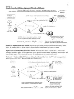
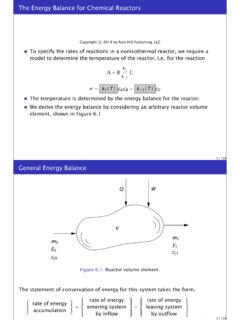
4 A standard process engineering computing environment is desirable in any workplace. This reduces learning curves and increases Software usage. PRO/II provides an environment where this happens and, in turn, produces engineers that spend less time simulating process problems and more time implementing process improvements. In this example we will use conversion, equilibrium, and adiabatic Gibbs reactors, as well as heat exchangers and controllers. Consider a process stream at 39oF and 390 psia shown as stream S1 in Figure 1.
5 Table 1 lists the flow rates of all components in stream S1. Table 1 Feed stream flow rate Component H2 N2 CO CO2 Flow rate, lbmol/h 10,000 5,000 50 5 We want to remove carbon monoxide and carbon dioxide in the feed by methanation reactions shown in equations (1) and (2). The product stream is then cooled to 25oF using ammonia at 25oF and 20 psia. 4H2 + CO2 CH4 + 2H2O (1) 3H2 + CO CH4 + H2O (2) Since the methanation reactions are exothermic, the product stream leaving the Reactor is used to preheat the feed stream before it transfers heat to the ammonia stream entering the heat exchanger E2 at 25oF and 20 psia.
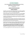
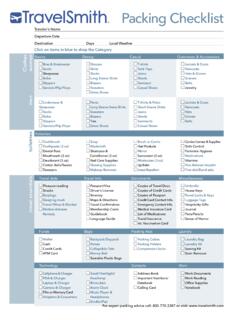
6 2 Figure 1 Schematic of the Reactor setup. To open Provision, go to the Start menu, click on Programs, Simsci, and then ProII 6. The following screen should appear: Note the different colored boxes and their meanings. They will be very important to remember later on in the Simulation . Click on OK at the bottom of the box to continue 3into the Simulation environment. Next, click on File and then New. This should bring you to the following screen: This is the basic Simulation environment from which you will begin each time you use Provision.
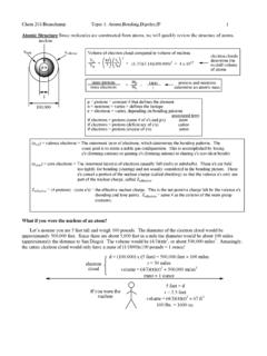
7 It is called the PFD screen. Before you begin with the procedure given to you in the assignment, you need to enter the components that you will be using and your equation of state. First click on the Component Selection button on the top toolbar. This button looks like this: . The following screen should appear: 4 From here you can either type in the names of your desired components or you can select them from a list already inside Provision. We will select our components from a list by clicking on the Select from Lists button.
8 The following screen should appear: In this example, all of the needed components can be found in the Most Commonly Used file. Click on it and select each of the components listed in the first column of Table 2. After you click Add Components, the selected species will appear in the bottom text box Additions to Component List. Table 2 Data for Simulation Feed H2 10000 Lb-Mol/Hr N2 5000 CO 50 CO2 5
9 CH4 0 NH3 0 H2O 0 Temp.
10 39 F Pressure 390 Psia Products Temp. 25 F As little CO and CO2 as possible. You have an ample supply of ammonia at 25 F and Psia. Pressure drop per side of exchanger/ Reactor = Psia Temperature Rise in all equilibrium and conversion reactors = 10 F 5 After you selected all species click OK to return to the following screen.