Transcription of RF Mixers - QSL.net
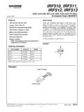
1 RF Mixers Iulian Rosu, YO3 DAC / VA3 IUL, RF Mixers are 3-port active or passive devices. They are designed to yield both, a sum and a difference frequency at a single output port when two distinct input frequencies are inserted into the other two ports. In addition to this, a Mixer can be used as a phase detector or as a demodulator. The two signals inserted into the two input ports are usually the Local Oscillator signal, and the incoming (for a receiver) or outgoing (for a transmitter) signal. To produce a new frequency (or new frequencies) requires a nonlinear device. In a mixing process if we want to produce an output frequency that is lower than the input signal frequency, then it is called down-conversion and if we want to produce an output signal that is at a higher frequency than the input signal, it is referred to as up-conversion.
2 A down-conversion system An up-conversion system A common misunderstanding about Mixers is that a Mixer is only a nonlinear device. Actually, an RF Mixer is fundamentally a linear device, which is shifting a signal from one frequency to another, keeping (faithfully) the properties of the initial signal (phase and amplitude), and therefore doing a linear operation. An RF Mixer is a frequency translation device which: - Convert RF to a lower IF or baseband for easy signal processing in receivers - Convert IF frequency (or baseband signal) to a higher IF or RF frequency for efficient transmission in transmitters. From the moment that we use a nonlinear device to perform the mixing operation, Mixers have relatively high levels of intermodulation distortion, spurious responses, and other undesirable nonlinear phenomena.
3 In contrast to frequency multipliers and dividers, which also change signal frequency, Mixers theoretically preserve the amplitude and phase without affecting modulation properties of the signals at its ports. Mixers creative use of nonlinearity or time-variance phenomenon s, which are usually harmful and unwanted for an RF system RF Mixers generates frequencies not present at their input and used together with appropriate filtering they remove unwanted frequencies. RF Mixers use two operation mechanisms: - Nonlinear transfer function, which use device nonlinearities creatively in a matter that intermodulations creates the desired frequency and unwanted frequencies. - Switching or sampling is a time-varying process. This method is preferred because has fewer spurs and can provide higher linearity.
4 Important properties of an RF Mixer are: Conversion Gain or Loss - lowers the noise impact of following stages. Intercept Point (Linearity) - impacts receiver blocking and interferer performance. Ports Isolation (LO-to-RF, LO-to-IF, RF-to-IF) - want to minimize interaction between the RF, IF, and LO ports. Noise Figure - impacts receiver sensitivity. High-order spurious response rejection. image Noise suppression improves system noise figure. Operating Frequency Range. 1. Conversion Gain or Loss of the RF Mixer is dependent by the type of the mixer (active or passive), is dependent by the load of the input RF circuit as well the output impedance at the IF port, and also is dependent by the level of the LO. Conversion Gain or Loss is the ratio of the desired IF output (voltage or power) to the RF input signal value (voltage or power).
5 If the input impedance and the load impedance of the mixer are both equal to the source impedance, then the voltage conversion gain and the power conversion gain of the mixer will be the same in dB s The typical conversion gain of an Active Mixer is approximately +10dB, when the conversion loss of a typical Diode Mixer is approximately -6dB. The Conversion Gain or Loss of the RF Mixer measured in dB is given by: Conversion[dB] = Output IF power delivered to the load[dBm] RF input power[dBm] 2. Input Intercept Point (IIP3) is the RF input power at which the output power levels of the unwanted intermodulation products and the desired IF output would be equal. From RF System point of view, Mixer linearity is more critical than its Noise Figure. In a receiver, the most damaging distortion products are odd-order, since those are most likely fall within the same passband as the desired signal.
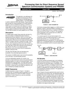
6 The highest amplitude will be the lowest order, , the 3rd order products. The most common figure of merit for intermodulation distortion (IMD) is Third Order Intercept (TOI). The Third-Order Intercept point (TOI or IP3) in a Mixer is the fictional value defined by the extrapolated intersection of the primary IF response with the two-tone 3rd intermodulation IF product that results when two RF signals are applied to the RF port In any application where IIP3 is very important, a large LO power is required. The LO (Local Oscillator) provides switching of the signal input, interrupting or redirecting the signal current. Both, Diode and FET Mixers can benefit from LO switching. Silicon bipolar transistors (BJTs) do not switch well above Ft/10, thus degrading IIP3 and NF. In a well designed passive Diode Mixer should get: IIP3[dB] ~ LO[dBm] + 9dB Because the LO voltage is applied from the gate to the source-drain, and the signal flows from source to drain, there is an independence that allows FETs to have a higher IIP3 for a given LO drive than a Diode Mixer.
7 The gate to channel impedance is very high, while the channel drain to source resistance is low. In passive FET Mixers , the gate input which is driven by the LO looks like a high-Q, capacitor. After tuning out this capacitance, the real LO power required to drive the mixer with a large voltage at frequency F is reduced by a factor of GMAX . Therefore, for FET Mixers : IIP3[dBm] ~ LO[dBm] + 9dB + 20 LOG(GMAX) (Where GMAX = Maximum available Gain at Frequency F) This shows why FETs with a high Fmax make better passive Mixers than diodes. Nonlinearity in RF Input Path is the same as in LNA nonlinearity case. As in case of the LNA this nonlinearity can be characterized with IIP3 and using a two-test to measure. 3. Spurious Products in a Mixer are problematic, and Mixer vendors frequently provide tables showing the relative amplitudes of each response under given LO drive conditions.
8 One way to reduce such products is to short-circuit the higher harmonics of the LO at the intrinsic Mixer terminals to lower the power in such responses. Reducing the 2nd or 3rd harmonic of the local oscillator reduces its harmonic products by 20 to 25dB, and 10 to 15dB, respectively. 4. Isolation is the amount of local oscillator power that leaks into either the IF or the RF ports. There are multiple types of isolation: LO-to-RF, LO-to-IF and RF-to-IF isolation. Self-Mixing of Reverse LO feed-through: - LO component in the RF input can pass back through the mixer and be modulated by the LO signal, and a DC and 2fo components are created at the IF output. - This has no consequence for a heterodyne system, but can cause problems for homodyne systems ( , zero IF) LO to RF port isolation is by far the biggest short coming 5.
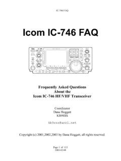
9 Noise Figure is a measure of the noise added by the Mixer itself, noise as it gets converted to the IF output. For a passive Mixer which has no gain and only loss, the Noise Figure is almost equal with the insertion loss. In a mixer noise is replicated and translated by each harmonic of the LO that is referred to as Noise Folding. In addition to the degradation in system Noise Figure introduced by the conversion loss of the Mixer, noise sources within the Mixer device itself further corrupt the Noise Figure. For example, the effect of 1/f noise in MESFETs can be severe if the IF frequency is below the corner frequency of the flicker noise (normally less than 1 MHz), as this noise will add to the output. Broadband noise from the input of the mixer will be located in both image and desired bands.
10 Noise from both, image and desired bands, will combine in desired channel at IF output. A Mixer will convert energy in the upper or lower sidebands with equal efficiency. Consequently, the noise in the side band with no signal will be added to the IF output, which will increase the Noise Figure at the IF port by 3dB, no matter how good the preceding component noise figure is. Typically, Mixers are noisier than amplifiers due to the noise folding nature of Mixers An image Filter at the RF input of the Mixer could suppress this noise. Particular image Reject Mixers can suppress the image noise by their topology. image Noise and image Filter The wideband noise of the Local Oscillator (LO) is another parameter that can raise the IF noise level, degrading in this way the overall Noise Figure.


![and Super-Resolution arXiv:1603.08155v1 [cs.CV] 27 Mar 2016](/cache/preview/2/d/c/1/c/a/1/5/thumb-2dc1ca15e82fc13a292da02b4114d430.jpg)
