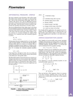
Transcription of RTD STANDARDS - Gilson Eng
1 RTD STANDARDSM aximum Operating Range = -195 C to 660 C (-383 F to 1475 F)Note: RTD s are not commonly used above 900 F. However, JMSoffers a special high temperature RTD which will withstand temper-atures up to 1560 = .25 C at 0 CStability = Less than .05 C shift per Operating Current = 1 Safe Current = 20 Resistance = 100 mega ohms minimum at 50 Encapsulation = High purity alumina constant for RTD element without tubing = 1 second maxi-mum for the sensor to reach of a step change in tempera-ture in water at 3 feet per probes will usually not have a transition if the lead wires areless than 12 in standard accuracy of JMS Southeast s RTD is .1% of resis-tance at 0 C . Accuracies of.
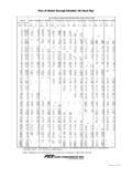
2 03% and .01% of resistance at 0 Care also Southeast bulbs are aged as part of the manufacturingprocess, thus ensuring high levels of stability. Generally the resis-tance at 0 C will hold less than a .05 C shift per detectors can withstand a vibration level of 30g over the fre-quency range 10 Hz to 1 RTD s are insensitive to large changes of TimeResponse time of JMS Southeast metal encapsulated probes isdependent on the outside diameter of the probe and the immersionmedia, usually matches that of the same size ungrounded thermo-couple. (See page 1-13)Self HeatingWhen tested in accordance with requirements of BS 1904: 1964 Section the indicated temperature rise in the temperaturedetector with a power of dissipated in it, will not exceed+.
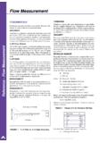
3 3 TEMPERATURE DETECTORSG eneral InformationA resistance temperature detector or platinum resistance thermometer works on the principle that the electricalresistance of a metal changes in a significant and repeatable way when temperature changes. This resistance isinversely proportional to cross sectional area and proportional to is the most widely used metal for resistance temperature detection due to the following characteristics:1) chemical inertness2) a temperature coefficient of resistance that is large enough to give readily measurable resistance changes with temperature3) an almost strain free fabrication metal (in that resistance doesn t drastically change with strain)4) an almost linear relation between resistance and temperatureEach resistance versus temperature relation for an RTD is qualified by a term known as alpha.
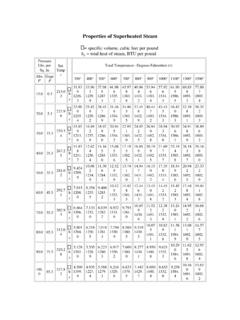
4 Alpha is theslope of the resistance between 0 C and 100 C. This is also referred to as the temperature coefficient of resistance,with the most common being / / types of RTD s manufactured include copper, nickel and nickel amount of resistance of an individual RTD bulb (100 , 200 , etc.) is determined by the amount of metalbetween the terminal points and by the configuration of the ordering an RTD, the alpha and resistance value at 0 C ( : Ro) must be specified to match the mea-suring instrumentation used with the RTD standard must also be specified. There are several RTD STANDARDS set by various specifications are not identical and read out instrumentation must be adjusted for the specific standard of the RTDused with that equipment.
5 Differences in the alpha values of these STANDARDS can cause errors in measurement of anRTD if one standard is connected to the instrumentation of another following chart indicates some common RTD (ohms)ORGANIZATION STANDARD ALPHAAT 0 CAmerican Scientific Apparatus RC21-4-1966 Association (SAMA)British STANDARDS Association 1904-1964 100 FachnormenausschuB DIN 43760 100 Elektrotchnek im DeutschenNormenausschuBInternational Electrotechnical IEC 751: 1983 100 Commission (Supersedes BS & DIN)US Department of Defense MIL-T-24388 100 Back To Home Table Of Contents Chapters 1-10 Order FormToleranceRESISTANCE TEMPERATURE DETECTORSS uper DIN-Meets DIN 43760, 751.
6 00385 ohms/ohms/ C, to1/10 design tolerance at initial bulb calibrationNot available in dual element swaged-Tip sensitivity = 1 + 1/2 -Probe can be manufactured as a 3/32 , 1/8 , 1/4 or larger tube3-11 .75 .5 .25-200-1000100200300400500ohms CStandard ToleranceDIN 43760, IEC 751( at 0C)*( at 0C)*Super DIN( at 0C)*Temperature C *Initial Calibration AccuracyTHERMOCOUPLES VS RTD STHERMOCOUPLERTD SAccuracyLimits of error wider thanLimits of error smaller thanRTDthermocouplesRuggednessExcellentS ensitive to strain, shock,and pressureTemperature-400 to 4200 F-200 to 1475 FSizeCan be as small as .01 Size limited to 1/16 , temperaturesheath material, tipsensitive for length of bulbsensitiveDriftShould be to C per year, lessperiodically, higher thandrift than thermocoupleRTD sResolutionMust resolve millivolts perOhms per degree, much higherdegree.
7 Lower signal to signal to noise ratio thannoise ratiothermocoupleColdRequiredNot requiredJunctionReferenceLead wireMust match lead wireCan use copper lead wire forcalibration to thermocoupleextension wirecalibrationResponseCan be made small enough Thermal mass restrictsfor millisecondtime to seconds or moreresponse timeCostLowHigher than thermocouplesThe following chart indicates some inherent advantages and disadvantages of RTD s or CONFIGURATION EXPLANATIONREDSYMBOL Z2 WIRE CONFIGURATIONF igure 1 WHITEREDSYMBOL Y3 WIRE CONFIGURATIONF igure 2 WHITEREDREDSYMBOL WSTANDARD4 WIRECONFIGURATIONWHITEREDWHITEIn the three wire configuration, the power supply is taken to one side of the resistance temperature the other two leadwires in opposite arms of the wheatstone bridge so that they cancel each other out and have lit-tle effect on the bridge output voltage.
8 In the 3 wire configuration, the resistance of the lead wire length is compensat-ed for in the Wheatstone bridge. This design is recommended for most industrial even more accurate wire configuration is the 4 wire design. In this design, leadwires #1 and #2 are on one sideof the power supply while leadwires #3 and #4 are on the other side of the power supply. All four leadwire resistancesin this case are negated and the bulb resistance stands as the resistance input alone. We strongly recommend thisdesign. You must have a good 4 wire input device. Call us for VUNCOMMON4 WIRECONFIGURATIONBLUEREDWHITEF igure 3 JMS RTD color codes are per ASTM E1137 and IEC 751 resistance temperature detector determines the temperature by measuring resistance.
9 The sensing element isusually a small diameter wire manufactured so that its resistance will change in a known and consistent the resistance accurately and consistently, other extraneous resistances must be compensated for or mini-mized. Amajor cause of extraneous resistance is leadwire in series with the RTD. The readout is the sum of the bulbresistance and the leadwire resistances. The leadwire resistance can be compensated in most applications by a threewire RTD leadwire OPERATION AND INSTALLATION INSTRUCTIONSRTD s are installed by means of compression fittings, welded or spring-loaded NPTfittings, or bayonet these instructions for installation of an RTD with a 1/2 x 1/2 NPTfitting:(1) Insert RTD into process hole or opening.
10 (2) Tighten probe into place by turning probe into threaded cold-end termination of the RTD is wired into head and you have a spring loaded fitting, then the wires should be dis-connected from the terminal block to prevent twisting and :Make sure the extension wire is clean so that a good electrical connection will result at the terminal block. Werecommend the use of a lacquer, cement, or other moisture proof sealing to prevent oxidation and the loosening of ter-minals. Connect the positive extension wire to the positive RTD wire and the negative extension wire to the negativeRTD wire. Wires are color coded for identification as follows:Two Wire Configuration:Connect the white wire to the positive connection terminal and connect the red wire to the negative connection Wire Configuration:The two red wires are common.