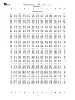
Transcription of RTD THERMOMETER MODEL NO. 60010-85 - Fisher Scientific
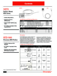
1 DataLogRRTD THERMOMETERMODEL NO. 60010-85 Digi -Sense Digi -Sense Digi -Sense CERTIFICATE OFCONFORMANCEThis THERMOMETER was calibrated usingequipment traceable to the National Insti-tute of Standards and Technology (NIST).This instrument conforms toDIN IEC-751 revised to accuracy of the THERMOMETER at thetime of calibration was within specificationsstated in the operating No.:_____Serial Number:_____Date placed in service:_____To purchase an NIST certificate of trace-ability with test data and test date for meterand probe, please contact your dealer or:Barnant Company28W092 Commercial AvenueBarrington, Illinois USA 60010-2392 Toll-free: 800-637-37391 INTRODUCTIONThis versatile hand-held instrument provides highlyaccurate temperature measurements in Celsius orFahrenheit using a 100 ohm platinum rtd , with analpha of or instrument covers the extended measuringrange of 200 to 1210 C ( 328 to 2210 F).
2 The instrument is designed for easy operation andincludes the following features: Operator selection of temperature scale Resolution of from C to C ( F to F) LCD with three four-digit displays 3-pin circular connector input (mate to SwitchcraftTA3F plug) Hold feature for temporarily retaining a reading Two-point field calibration capability Low battery warning Stores or logs up to 1000 readings with real-timemarkers2 Scrolls through all stored readings Displays MIN and MAX readings Interfaces with optional HEWLETT PACKARD infrared printer or optional RS-232-C adapter Prints temperature and time of reading Built-in tilt stand for easy hands-free operationSAFETY PRECAUTIONSVOLTAGES PRESENT ATTHE RTD MAY ALSO BEPRESENT AT THE BATTERY DISCONNECT THE RTD WHENCHANGING INSTRUMENT ISDESIGNED TO ACCEPTLOW LEVEL SIGNALS SUPPLIED BY STANDARD100 OHM platinum RTD S. UNDER NOCIRCUMSTANCES SHOULD THE INPUTVOLTAGE EXCEED THE SPECIFIED 10 V NOT USE OR STORETHIS INSTRUMENT INMICROWAVE OVENS OR ANY ABNORMALLYHOT OR COLD BATTERIES SHOULDNOT BE LEFT IN THEINSTRUMENT.
3 DEAD BATTERIES CAN LEAKAND CAUSE DAMAGE TO Declaration of ConformityName of Apparatus: RTD LoggerModel Number: 60010-85 *Description of Apparatus: Electronic thermometerusing an RTD probeBarnant Company declares that the above MODEL isin conformity to the following harmonized standardsand directives:Applicable ApplicableManufacturer sDirectivesSpecificationsReport Number73/23/EECEN61010-1/A2: 1995 TR007693/68/EEC89/336/EEC EN61326-1/A1: 1998TR007692/31/EEC93/68/EECThe last two digits of the year in which the currentconfiguration of the above MODEL was assessed perthe Low Voltage Directive is :00.*Evaluated for EMC as part of a system using theAC Adapter, MODEL Number :Barnant Company DivisionCole-Parmer Instrument Company28W092 Commercial AvenueBarrington, IL 60010-2392 USATel.: 847-381-7050 Manufacturer s Signature:James W. DollDateVice President, Engineering19 December, 20004 SPECIFICATIONSRTD PROBESI mpedance: 100 ohm @ 0 C (32 F)Sensitivity (alpha): or ohm/ohm/ C selectableAccuracy: F.
4 C at resolution at resolution 1 at 1 resolutionLOGGERL inearization: Conforms to DIN IEC 751, revisedto ITS-90 Input Protection: 10V rmsDisplay Update: seconds per updateConnector: 3-pin circular connector input (mateto Switchcraft TA3F plug)BatterySize: Two AA, alkaline ANSI-L40,IEC-LR6 Life:>300 hours continuous, typicalDisplay:LCD with in high characters mainreadout and in high characters secondarydisplays, 4 digits each display plus RangeOperating:Stated Accuracy:10 C to 40 C(50 F to 104 F)Useful Range:0 C to 40 C(32 F to 104 F)Storage: 10 C to 60 C( 14 F to 140 F)Humidity:10% to 90%(non-condensing)5 Dimensions3 cm D x cm W x cm H( in x in x in)Weight with batteries: 227 grams (8 ounces)Ingress protection: Meets IEC-529 IP-54 for dustand water resistant :For CE Mark:EN61326-1/A1: 1998(EU EMC Directive)6 BATTERY INSTALLATION ANDREPLACEMENTVOLTAGES PRESENT ATTHE RTD MAY ALSO BEPRESENT AT THE BATTERY DISCONNECT THE RTD WHENCHANGING BATTERIES SHOULDNOT BE LEFT IN THEINSTRUMENT.
5 DEAD BATTERIES CAN LEAKAND CAUSE DAMAGE TO battery indicator turns on, battery life isapproximately 8 to 10 hours. The battery indicatorwill start blinking with less than 1 hour of THIS POINT, BATTERY MUST BE BATTERY VOLTAGE GOES TOO LOW, DISPLAYWILL GO SPECIFICATIONS for battery Before changing battery, turn instrument off anddisconnect Loosen screw and lift battery cover off back Remove the two AA Insert two new batteries, observing Install cover and tighten ADAPTERAn optional AC adapter can be used for power toconserve batteries. The adapter is not a chargerand will not charge batteries. The adapter connectsto the bottom of the THERMOMETER . When the adapteris connected, the batteries are disconnected. Referto the ACCESSORIES section for AN RTDNote: Be sure your instrument setting matches theRTD you are using (alpha of or ).See SELECTING RTD SENSITIVITY (ALPHA)on page 14. Insert the 3-pin plug into the matingconnector on the top of the SETUPNote: Review SAFETY PRECAUTIONS on page Install Connect RTD Press the ON/OFF key.
6 The THERMOMETER performsa self-test and all display digits and indicators,as shown below, should remain on forapproximately one clock will remain on for about three Use SETUP to select the correct sensitivity(ALPHA) and various other options. Use or to make selections, to enter selections andgo to next a probe has not yet been connected to theinstrument, you will see this display:This message also appears if a probe is measurements can be made while this warningis FACTORY DEFAULTSP ress and hold CLEAR and SETUP at power onuntil CLr shows in the display. Then releaseCLEAR and SETUP. Press any key to SETUP PROCEDUREThe setup function scrolls through a series of stepsfor selecting probe sensitivity (alpha), resolution, filterrate, setting the real-time clock, selecting the linefrequency and accessing the Log sub-menu and thePrint sub-menu. Either the complete setup can berun as described below, or the setup can be initiatedand terminated at any step.
7 The Log sub-menu andthe Print sub-menu can be accessed without goingthrough the complete setup. These variations arecovered in the following selected in the Setup procedure are storedin memory and will remain even after power isturned off or while batteries are being the SETUP key. The lower left display willshow either the time of day or OFF and it will LOWER DISPLAY MODEP ress the MAX key or MIN key to toggle thelower display between showing the time of day andshowing minimum and maximum temperaturevalues. Press the HOLD key to advance to thenext step in the setup RTD SENSITIVITY (ALPHA)Press the MAX key or MIN key to select (3850 flashing) or (3916flashing). The lower left display will read ALPH .When correct RTD sensitivity is flashing, pressthe HOLD key to advance to the next step inthe setup RESOLUTIONT here are three choices for temperature first choice is with resolution selected:the THERMOMETER will automatically range to show15the greatest possible resolution.
8 The next choice resolution: the THERMOMETER will automaticallyrange between and 1 as required. The finalchoice is 1 resolution: the display will remain inthis resolution for all displayed or resolution is selected, a decimalpoint will appear in the upper numerical display. When1 resolution is selected, no decimal point will upper display will show , or 1 and itwill be flashing. Press either MAX key or MIN key to change resolution, then press the HOLDto advance to the next step in the RATEThe filter rate can be set to OFF, Lo or Hi. This rateis changed to smooth out fluctuations in thereadings. Normally this would be set to OFF. Ifreadings are unstable, try changing to Lo or lower left display will read FILt and the upperdisplay will flash either OFF, Lo or Hi. Use the MAX key or MIN key to switch the filter rate, thenpress HOLD key to store the rate and continuesetup by setting the real-time REAL-TIME CLOCK1.
9 When setting the real-time clock, the right twodigits in the lower left display will be the MAX key or MIN key to adjust theflashing digits to the desired minute Press HOLD key to lock in the minutes andadvance to the hours are set in the 24 hour time system. Therefore,time after 12:59 pm requires 12 to be added to thetime. For example, 3:00 PM is (3+12) = 15:00 The left two digits in the lower left display willbe flashing. Use the MAX key or MIN keyto adjust the flashing digits to the desired Press the HOLD key to store the hours andadvance to the month The MO annunciator will be on and the left twodigits in the lower right display will be the MAX key or MIN key to adjustthe flashing digits to the desired month setting(1 to 12).6. Press the HOLD key to store the monthsand advance to the day The DAY annunciator will be on and the righttwo digits in the lower right display will beflashing.
10 Use the MAX key or MIN key toadjust the flashing digits to the desired daysetting (1 to 31).8. Press the HOLD key to store the day andadvance to the year The YR annunciator will be on and the two digitsin the lower left display will be flashing. Use theMAX key or MIN key to adjust the flashingdigits to the desired year setting (2000 to 2063).10. Press the HOLD key to lock in the year. Toset up the log or print functions proceed to thefollowing FREQUENCY SELECTIONFor maximum noise rejection, it is possible to selectone of two line frequency settings. This selectionshould be based on the local mains power linefrequency of either 50 Hz or 60 Hz. For example, allof North America is 60 Hz, while Europe is 50 lower left display will show LINE while theupper display is flashing either 50 or 60. Use theMAX key or MIN key to adjust the flashingdigits to the desired line frequency the HOLD key to lock in the linefrequency.