Transcription of Selectable Output Strobes, Horns, and Horn ... - System Sensor
1 1 I56-2769-022 5/22/2019 INSTALLATION AND MAINTENANCE INSTRUCTIONSS electable Output Strobes, Horns, and Horn/Strobes3825 Ohio Avenue, St. Charles, Illinois 60174800/736-7672, FAX: 630 use with the following models: P2R, P2RH, P2RK, P2 RHK, P2W, P2WK, P2WH, P2 WHK, P4R, P4RH, P4RK, P4W, P4WK, P4 WHK-P, SR, SRH, SRK, SRHK, SW, SWK, SWH, SWHK, SW-CLR-ALERT, PC2R, PC2RH,PC2RK, PC2 RHK, PC2W, PC2WK, PC2WH, PC2 WHK, PC4R, PC4RH, PC4W, PC4WK, PC4 WHK, SCR, SCRH, SCRK, SCRHK, SCW, SCWK, SCWH, SC-WHK, SCW-CLR-ALERT, HR, HRK, HW, SR-P, SW-P, SRH-P, SWH-P,P2R-P, P2W-P, P2WH-P, P4R-P, P4W-P, SCW-P, PC2R-P, PC2W-P, PC2WH-P, SRK-P, SRHK-P, P2RK-P, P2 RHK-P, SWK-P, SWHK-P, P2WK-P, P2 WHK-P, SR-SP, P2R-SP, PC2W-SP, SRK-R, SWK-R, SRHK-R, SWHK-R, P2RK-R, P2WK-R.
2 P2 RHK-R, P2 WHK-R, SBHK, SBK-R. NOTES: Refer to your panel documentation or models listed for use with specific panels. NOTE: All -R models are specifically designed for use with the WTP Series of Weatherproof plates. NOTE: When replacing outdoor units; device and back box must be : Models SBHK, SBK-R are UL listed for General SPECIFICATIONSO perating Temperature:Standard Products32 F to 120 F (0 C to 49 C)K Series 40 F to 151 FHumidity Range:Standard Products10 to 93% Non-condensingK SeriesMeets NEMA 4X requirementsStrobe Flash Rate:1 flash per secondNominal Voltage:Regulated 12 VDC/FWR or regulated 24DC/FWRO perating Voltage Range (includes fire alarm panels with built in sync).
3 8 to (12V nominal) or 16 to 33V (24V nominal)Operating Voltage with MDL3 Sync to (12V nominal) or to 33V (24V nominal)Input terminal wire gauge:12 to 18 AWGNOTE : Strobes will operate at 12 V nominal for 15 & 15/75 candela settings only. Switching between ranges is FOR PRODUCTS AND ACCESSORIESWALL PRODUCTSL engthWidthDepthCEILING PRODUCTSDIAMETERDEPTHS trobe and Horn/Strobes (including lens) " " "Strobes and Horn/Strobes(including lens) " "142 mm119 mm64 mm173 mm64 " " "SA-WBBC Red Weatherproof Back " "142 mm119 mm33 mmSA-WBBCW White Weatherproof Back Box180 mm51 mmSA-WBB Red Weatherproof Back " " "SBBCR Red Surface Mount Box " "SA-WBBW White Weatherproof Back Box145 mm130 mm51 mmSBBCW White Surface Mount Box175 mm135 mmSBBR Red Surface Mount " " "NOTE.
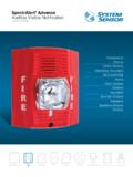
4 SA-WBB, SA-WBBW, SA-WBBC and SA-WBBCW dimensions do not include the two mounting tabsSBBW White Surface Mount Box142 mm119 mm109 mmMOUNTING BOX OPTIONS2-Wire Indoor Products4-Wire Indoor ProductsK Series Products4 4 11/2, Single Gang, Double Gang, 4" Octagon SBBR/W (wall), SBBCR/W (ceiling)4 4 11/2, Double Gang, 4" OctagonSA-WBB/W (wall), SA-WBBC/CW (ceiling)GENERAL DESCRIPTIONThe SpectrAlert Advance series of notification appliances offers a wide range of horns, strobes, and horn/strobes, for wall and ceiling applications, indoors and outdoors.
5 They are designed to be used on 12 or 24 volt, DC or FWR (full wave rectified) systems. These products are electrically backward compat-ible with the previous generation of SpectrAlert notification appliances. Horn/strobe products are available in two versions. The 2-wire products fit systems where a single NAC controls both horn and strobe. The 4-wire products are in-tended for systems which have separate wiring circuits for the horn and strobe. All SpectrAlert Advance products are suitable for use in synchronized systems.
6 The System Sensor MDL3 module may be used to provide Series products are designed to be used over a wider range of temperatures and are suitable for use in wet environments with outdoor backbox supplied with product. Wall and ceiling products may be used interchangeably (wall products may be used on the ceiling and ceiling products may be used on the wall.)FIRE ALARM System CONSIDERATIONSThe National Fire Alarm Code, NFPA 72, requires that all horns, used for building evacuation produce temporal coded signals. Signals other than those used for evacuation purposes do not have to produce the temporal coded sig-nal.
7 System Sensor recommends spacing notification appliances in compli-ance with NFPA DESIGN AND WIRINGThe System designer must make sure that the total current drawn by the de-vices on the loop does not exceed the current capability of the panel supply, and that the last device on the circuit is operated within its rated voltage. The current draw information for making these calculations can be found in the tables within this manual. For convenience and accuracy, use the voltage drop calculator on the System Sensor website ( ).When calculating the voltage available to the last device, it is necessary to consider the voltage drop due to the resistance of the wire.
8 The thicker the wire, the smaller the voltage drop. Wire resistance tables can be obtained from electrical handbooks. Note that if Class A wiring is installed, the wire length may be up to twice as long as it would be for circuits that are not fault : The total number of strobes on a single NAC must not exceed 40 for 24 volt applications or 12 for 12 volt applications. Loop resistance on a single NAC should not exceed 120 ohms for 24 volt and 30 ohms for 12 volt : This manual shall be left with the owner/user of this equipment.
9 2 I56-2769-022 5/22/2019 CANDELA SELECTIONA djust the slide switch on the rear of the product to the desired candela set-ting in the small window on the front of the unit. All products meet the light Output profiles specified in the appropriate UL Standards. See Figures 1-3. Use Table 1 to determine the current draw for each candela setting.
10 For K series products used outdoors at low temperatures, listed candela ratings must be reduced in accordance with Table 2. NOTE: SpectrAlert products set at 15 and 15/75 candela automatically work on either 12V or 24V power supplies. The products are not listed for 12V op-erating voltages when set to any other candela settings. For 4-Wire products, total current draw may be determined by adding current draw for the specific candela selection and the current draw for the specific horn selection use Table 1 and Table 1.