Transcription of Sensorless BLDC Control AN1160B - Microchip Technology
1 2008-2012 Microchip Technology 1AN1160 INTRODUCTIONThis application note describes a Sensorless BrushlessDirect Current ( bldc ) motor Control algorithm that isimplemented using a dsPIC Digital Signal Controller(DSC) or a PIC24 microcontroller. The algorithm worksutilizing a majority function for digitally filtering theBack-Electromotive Force (BEMF). Each phase of themotor is filtered to determine when to commutate themotor drive voltages. This Control technique excludesthe need for discrete, low-pass filtering hardware andoff-chip comparators. It should be pointed out that allthe discussions here, and the application software,assume a 3-phase motor has to be used. The motorcontrol algorithm described here has four main parts: Sampling trapezoidal BEMF signals using the microcontroller s Analog-to-Digital Converter (ADC) PWM ON-side ADC sampling to reduce noise and solve low-inductance problems Comparing the trapezoidal BEMF signals to VBUS/2 to detect the zero-crossing points Filtering the signals coming from the comparisons using a majority function filter Commutate the motor driving voltages in three different modes:- Classic Open Controller- Classic Closed-Loop Controller- Proportional-Integral (PI) Closed-Loop ControllerThis new Control method is a single-chip 16-bit PIC MCU or dsPIC DSC device-based solution.
2 The onlyexternal hardware required is a few resistors, used toreduce the BEMF signals to the operational voltagerange of the device s ADC Control VERSUS Sensorless CONTROLThe bldc motor is used for both consumer and indus-trial applications due to its compact size, controllabilityand high efficiency. Increasingly, it is also used in auto-motive applications to eliminate belts and hydraulicsystems, to provide additional functionality and toimprove fuel economy, while reducing maintenancecosts to zero. Since the electrical excitation must be synchronous tothe rotor position, the bldc motor is usually operatedwith one or more rotor position sensors. For reasons ofcost, reliability, mechanical packaging and especially ifthe rotor runs immersed in fluid, it is desirable to run themotor without position sensors, which is commonlyknown as Sensorless is possible to determine when to commutate themotor drive voltages by sensing the BEMF voltage onan undriven motor terminal during one of the drivephases.
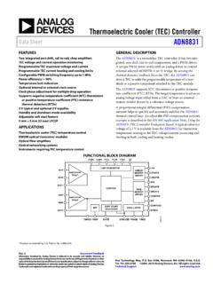
3 There are some disadvantages to sensorlesscontrol, however: The motor must be moving at a minimum rate to generate sufficient BEMF to be sensed Abrupt changes to the motor load can cause the BEMF drive loop to go out of lockIf low cost is a primary concern, if low-speed motoroperation is not a requirement, and if the motor load isnot expected to change rapidly, Sensorless trapezoidalcontrol may be a better choice for your , there are specific algorithms to overcome allof the above listed disadvantages. The BEMF zero-crossing technique described here isrecommended for several reasons: It is suitable for use on a wide range of motors It can, in theory, be used on both Y and delta-connected 3-phase motors It requires no detailed knowledge of motor parameters It is relatively insensitive to motor manufacturing tolerance variationsAuthor:Adrian Lita and Mihai ChelesMicrochip Technology bldc Control with Back-EMF Filtering Using a Majority FunctionAN1160DS01160B-page 2 2008-2012 Microchip Technology (Trapezoidal) CommutationThe method for energizing the motor windings in thesensorless algorithm, described in this applicationnote, is six-step trapezoidal or 120 1 shows how six-step commutation works.
4 Eachstep, or sector, is equivalent to 60 electrical sectors make up 360 electrical degrees or oneelectrical 1:SIX-STEP COMMUTATIONThe arrows in the winding diagram show the directionin which the current flows through the motor windingsin each of the six steps. The graph shows the potentialapplied at each lead of the motor during each of the sixsteps. Sequencing through these steps moves themotor through one electrical COMMUTATION Step 1- Red winding is driven positive. - Green winding is driven negative. - Blue winding is not driven. Step 2- Red winding remains positive. - Blue winding is driven negative. - Green winding is not driven. Step 3- Green winding is driven positive. - Blue winding is driven negative. - Red winding is not driven.
5 Step 4- Green winding is driven positive. - Red winding is driven negative. - Blue winding is not driven. Step 5- Blue winding is driven positive. - Red winding is driven negative. - Green winding is not driven. Step 6- Blue winding is driven Green winding is driven negative. - Red winding is not every sector, two windings are energized and onewinding is not energized. The fact that one of the wind-ings is not energized during each sector is an importantcharacteristic of six-step Control that allows for the useof a Sensorless Control 123456 Blue WindingGreen WindingRed WindingSector+VDCGND+VDCGNDGND+VDC 2008-2012 Microchip Technology 3AN1160 Generating and Sensing BEMFWhen a bldc motor rotates, each winding generatesBEMF, which opposes the main voltage supplied to thewindings in accordance with Lenz s law.
6 The polarity ofthis BEMF is in the opposite direction of the energizingvoltage. BEMF is mainly dependent on three motorparameters: Number of turns in the stator windings Angular velocity of the rotor Magnetic field generated by rotor magnetsBEMF can be calculated in terms of these parametersand angular velocity using Equation 4:EQUATION 1:BACK-EMF (BEMF)If magnetic saturation of the stator is avoided, or thedependency of the magnetic field on temperature isignored ( , B is constant), the only variable term is therotor s angular speed. Therefore, BEMF is proportionalto the rotor speed; as the speed increases, the frequency at which the sectors are sequenceddetermines the speed of the motor; the faster that thesectors are commutated, the higher the mechanicalspeed is achieved.
7 The BEMF voltage is proportional tothe rotor s speed. Because of this, detection of positionusing the BEMF at zero and very low speeds is notpossible. Nevertheless, there are many applications( , fans and pumps) that do not require positioningcontrol or closed-loop operation at low speeds. Forthese applications, a BEMF sensing method is veryappropriate. The commutated voltage applied to the stator also hasa direct impact on the correct functioning of the efficient Control , the applied voltage must be atleast enough to match to generated BEMF, plus thevoltage drop across the motor s windings due to torqueproduction. This voltage drop, in turn, is equal to theimpedance of the windings times the speaking, if the commutated voltage is set tomaximum, regardless of the motor s speed or torqueproduction, the motor will be driven inefficiently with thewasted energy heating the motor s windings.
8 For theproper Control necessary, Pulse-Width Modulation(PWM) is used to achieve the right voltage level. PWMis an efficient method of driving the motor, but it intro-duces some noise issues when attempting to acquirethe Control feedback signals ( , BEMF voltages).To summarize, the important relationships for bldc motors and Sensorless Control are: The magnitude of the BEMF signal is proportional to speed The frequency of the BEMF signal is equal to the (mechanical) rotational speed times the number of poles pairs Motor torque is proportional to current (assuming the motor s temperature is constant) Motor drive voltage is equal to BEMF (propor-tional to speed) plus winding impedance voltage drop (proportional to current for a given torque)Zero-Crossing DetectionIn bldc motor Control theory, the stator s flux shouldbe 90 electrical degrees ahead of the rotor s flux formaximum torque generation.
9 As a consequence, formaximum torque, the phase current needs to be inphase with the phase BEMF voltage. For the 3-phase bldc motors considered, the phasesare shifted 120 from each other, so a convenientmethod for having a rotating rotor flux in the stator is thesix-step commutation scheme previously described,commutating each of the three-phase voltages 60 elec-trical degrees. At maximum torque and full load, thephase current should have the same waveform as thedriving voltage, neglecting the inductive reactance, andthe two signals need to be in-phase, as it can be seenwhen comparing Figure 2 (high current, load applied)with Figure 3 (low current, no load). Figure 6 shows theindividual idealized phase BEMF waveforms as well asphase current, assuming an efficient commutation witha certain load.
10 The BEMF phase voltage is centered at one-half of thedriving voltage. This means that any zero-crossing eventactually indicates an intersection of the BEMF waveformwith a point that is one-half of the supply voltage(VBUS/2). The zero-crossing point occurs at 30 electricaldegrees from the end of the last commutation, which isalso 30 degrees from the next commutation point. Themotor speed can thus be calculated from the time inter-val between two zero-crossing events. When the currentzero-crossing event is identified, a precise schedule forfuture commutation steps can be sector corresponds to one of six equal 60 por-tions of the electrical cycle (the sector numbering isarbitrary). Commutations occur at the boundary of eachof the sectors.