Transcription of Serial Quad I/O (SQI) Flash Memory
1 2015-2019 Microchip Technology Inc. DS20005119J-page 1 Features Single Voltage Read and Write Operations- or Serial Interface Architecture- Nibble-wide multiplexed I/O s with SPI-like Serial command structure - Mode 0 and Mode 3- x1/x2/x4 Serial Peripheral Interface (SPI) Protocol High Speed Clock Frequency- : 104 MHz max- : 80 MHz max Burst Modes- Continuous linear burst- 8/16/32/64 Byte linear burst with wrap-around Superior Reliability- Endurance: 100,000 Cycles (min)- Greater than 100 years Data Retention Low Power Consumption:- Active Read current: 15 mA (typical @ 104 MHz)- Standby Current: 15 A (typical) Fast Erase Time- Sector/Block Erase: 18 ms (typ), 25ms (max)- Chip Erase.
2 35 ms (typ), 50 ms (max) Page-Program- 256 Bytes per page in x1 or x4 mode End-of-Write Detection- Software polling the BUSY bit in status register Flexible Erase Capability- Uniform 4 KByte sectors- Four 8 KByte top and bottom parameter overlay blocks- One 32 KByte top and bottom overlay block- Uniform 64 KByte overlay blocks Write-Suspend- Suspend Program or Erase operation to access another block/sector Software Reset (RST) mode Software Protection- Individual-Block Write Protection with permanent lock-down capability - 64 KByte blocks, two 32 KByte blocks, and eight 8 KByte parameter blocks- Read Protection on top and bottom 8 KByte parameter blocks Security ID- One-Time Programmable (OTP) 2 KByte, Secure ID- 64 bit unique, factory pre-programmed identifier- User-programmable area Temperature Range- Industrial: -40 C to +85 C- Industrial Plus.
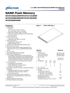
3 -40 C to +105 C Automotive AECQ-100 Grade 2 and Grade 3 Packages Available- 8-contact WDFN (6mm x 5mm)- 8-contact WDFN (6mm x 8 mm)- 8-lead SOIJ ( mm)- 16-lead SOIC ( mm)- 24-ball TBGA (6mm x 8mm) All devices are RoHS compliantProduct DescriptionThe Serial Quad I/O (SQI ) family of Flash -memorydevices features a six-wire, 4-bit I/O interface thatallows for low-power, high-performance operation in alow pin-count package. SST26VF064B/064BA alsosupport full command-set compatibility to traditionalSerial Peripheral Interface (SPI) protocol. Systemdesigns using SQI Flash devices occupy less boardspace and ultimately lower system members of the 26 Series, SQI family are manufac-tured with proprietary, high-performance CMOS Super- Flash technology.
4 The split-gate cell design and thick-oxide tunneling injector attain better reliability and man-ufacturability compared with alternate significantly improve perfor-mance and reliability, while lowering power consump-tion. These devices write (Program or Erase) with asingle power supply of The total energy con-sumed is a function of the applied voltage, current, andtime of application. Since for any given voltage range,the SuperFlash technology uses less current to pro-gram and has a shorter erase time, the total energyconsumed during any Erase or Program operation isless than alternative Flash Memory technologies. SST26VF064B/064BA are offered in 8-contact WDFN(6 mm x 5 mm or 6mm x 8mm), 8-lead SOIJ ( mm),16-lead SOIC ( mm), and 24-ball TBGA.
5 See Fig-ure 2-2 for pin configurations are available upon default at power-up has the WP# andHOLD# pins enabled, and the SIO2 and SIO3 pins dis-SST26VF064B / 64 Mbit Serial Quad I/O (SQI) Flash Memory 2015-2019 Microchip Technology Inc. DS20005119J-page 2 SST26VF064B / SST26VF064 BAabled, to initiate SPI-protocol default at power-up has the WP# andHOLD# pins disabled, and the SIO2 and SIO3 pinsenabled, to initiate Quad I/O operations. See I/O Con-figuration (IOC) on page 12 for more information aboutconfiguring WP#/HOLD# and SIO3/SIO4 pins. TO OUR VALUED CUSTOMERSIt is our intention to provide our valued customers with the best documentation possible to ensure successful use of your Microchipproducts.
6 To this end, we will continue to improve our publications to better suit your needs. Our publications will be refined andenhanced as new volumes and updates are introduced. If you have any questions or comments regarding this publication, please contact the Marketing Communications Department viaE-mail at We welcome your Current Data SheetTo obtain the most up-to-date version of this data sheet, please register at our Worldwide Web site at: can determine the version of a data sheet by examining its literature number found on the bottom outside corner of any last character of the literature number is the version number, ( , DS30000000A is version A of document DS30000000).ErrataAn errata sheet, describing minor operational differences from the data sheet and recommended workarounds, may exist for currentdevices.
7 As device/documentation issues become known to us, we will publish an errata sheet. The errata will specify the revisionof silicon and revision of document to which it determine if an errata sheet exists for a particular device, please check with one of the following: Microchip s Worldwide Web site; Your local Microchip sales office (see last page)When contacting a sales office, please specify which device, revision of silicon and data sheet (include literature number) you Notification SystemRegister on our web site at to receive the most current information on all of our products. 2015-2019 Microchip Technology Inc. DS20005119J-page 3 SST26VF064B / BLOCK DIAGRAMFIGURE 1-1:FUNCTIONAL BLOCK DIAGRAM25119 Buffer,I/O BuffersandData LatchesSuperFlashMemoryX - DecoderControl LogicAddressBuffersandLatchesHOLD#Y - DecoderCE#SIO [3:0] Serial InterfaceOTPWP#SCK 2015-2019 Microchip Technology Inc.
8 DS20005119J-page 4 SST26VF064B / PIN DESCRIPTIONFIGURE 2-1:PIN DESCRIPTION FOR 8-LEAD SOIJFIGURE 2-2:PIN DESCRIPTION FOR 8-CONTACT WDFNFIGURE 2-3:PIN DESCRIPTION FOR 16-LEAD SOIC12348765CE#SO/SIO1WP#/SIO2 VSSVDD HOLD/SIO3 SCKSI/SIO0 Top View25119 08-soic S2A #SO/SIO1WP#/SIO2 VSSTop ViewVDDHOLD/SIO3 SCKSI/SIO025119 08-wson QA #/SIO2 HOLD#/SIO3 VDDNCNCNCNCCE#SO/SIO116-SOIC View 2015-2019 Microchip Technology Inc. DS20005119J-page 5 SST26VF064B / SST26VF064 BAFIGURE 2-4:PIN DESCRIPTION FOR 24-BALL TBGATABLE 2-1: PIN DESCRIPTIONS ymbolPin NameFunctionsSCKS erial ClockTo provide the timing of the Serial , addresses, or input data are latched on the rising edge of the clock input, while output data is shifted out on the falling edge of the clock [3:0] Serial Data Input/OutputTo transfer commands, addresses, or data serially into the device or data out of the device.
9 Inputs are latched on the rising edge of the Serial clock. Data is shifted out on the falling edge of the Serial clock. The Enable Quad I/O (EQIO) command instruction configures these pins for Quad I/O Data Input for SPI modeTo transfer commands, addresses or data serially into the device. Inputs are latched on the rising edge of the Serial clock. SI is the default state after a power on reset. SOSerial Data Output for SPI modeTo transfer data serially out of the device. Data is shifted out on the falling edge of the Serial clock. SO is the default state after a power on #Chip EnableThe device is enabled by a high to low transition on CE#. CE# must remain low for the duration of any command sequence; or in the case of Write operations, for the command/data input #Write ProtectThe WP# is used in conjunction with the WPEN and IOC bits in the Configura-tion register to prohibit write operations to the Block-Protection register.
10 This pin only works in SPI, single-bit and dual-bit Read #HoldTemporarily stops Serial communication with the SPI Flash Memory while the device is selected. This pin only works in SPI, single-bit and dual-bit Read mode and must be tied high when not in SupplyTo provide power supply #NCWP#/SIO2 NCS0/SIO1SI/SIO0 HOLD# View 2015-2019 Microchip Technology Inc. DS20005119J-page 6 SST26VF064B / Memory ORGANIZATIONThe SST26VF064B/064BA SQI Memory array is orga-nized in uniform, 4 KByte erasable sectors with the fol-lowing erasable blocks: eight 8 KByte parameter, two32 KByte overlay, and one-hundred twenty-six64 KByte overlay blocks. See Figure 3-1: Memory MAP25119 of Memory Block8 KByte8 KByte8 KByte8 KByte32 KByte64 KByte64 KByte64 KByte32 KByte8 KByte8 KByte8 KByte8 KByteBottom of Memory Block4 KByte4 KByte4 KByte4 KByte.