Transcription of Single Pole (One location) or 3-Way (Multi ... - Leviton
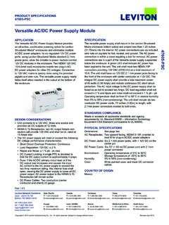
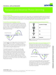
1 Disconnect wires from screw terminals or Quickwire slots (shown). Pull off pre-cut insulation from Dimmer leads. Make sure that the ends of the wires from the wall box are straight (cut if necessary). Remove 5/8" ( cm) of insulation from each wire in the wall box (shown). For Single -Pole Application, go to Step 5A. For 3-Way Application, go to Step Pole (One location) or 3-Way (Multi- location) Electronic Low-Voltage Slide DimmerCat. No. 6615-P 300W 120 VAC, 60 HzINSTALLATION INSTRUCTIONSDI-00X-06615-02 BTools needed to install your Dimmer:Slotted/Philips Screwdriver Electrical TapePliers PencilCutters RulerInstalling Dimmer by itself or with other devices:If installing Dimmer in a Single device application, proceed with the INSTALLING YOUR DIMMER section.
2 If installing Dimmer in a multi-device application, proceed as follows:MULTI-DEVICE APPLICATIONIn multi-dimmer installations, the reduction of the dimmer s capacity is required. Refer to the chart for maximum load per BULB WATTAGEThe maximum bulb wattage is determined by the efficiency of the transformer in the low-voltage lighting system. Transformer efficiencies will vary from different manufacturers; consider 80% efficient as average. Use the chart to determine maximum bulb wattage for typical transformer efficiency YOUR DIMMERNOTE: Use check boxes when Steps are completed. WARNING: To avoid fire, shock, or death; TURN OFF POWER at circuit breaker or fuse and test that power is off before wiring! Removing existing switch: Remove existing wallplate and switch mounting screws.
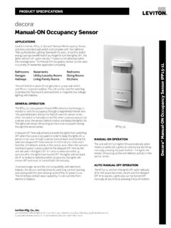
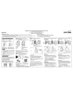
3 Carefully pull switch from wall box. DO NOT remove wires attached to the switch at this time. Identifying your wiring application (most common): NOTE: If the wiring in the wall box does not resemble any of these configurations, consult a qualified electrician. Step 2 Step 4 Step 1 Step 3 ONOFFONOFFONOFFONOFFONOFFONOFFONOFFONOFF ONOFFONOFFONOFFONOFFS ingle-Pole:Look at the back of your switch. If there are 2 wires connected to two screw terminals (not including a green or bare copper wire used for grounding), you have a Single -Pole switch. 3-Way :Look at the back of your switch. If there are 3 wires connected to three screw terminals (not including a green or bare copper wire used for grounding), you have a 3-Way switch. Note that one of the screw terminals will usually be a different color (black) or labeled Common.
4 Tag that wire with electrical tape to identify. WARNINGS: To be installed and/or used in accordance with appropriate electrical codes and regulations. If you are unsure about any part of these instructions, consult a qualified electrician. To avoid overheating and possible damage to this device and other equipment, do not install to control a receptacle, fluorescent lighting, a motor- or a transformer-operated appliance. Use with electronic low-voltage transformers only. Do Not use to control a magnetic low-voltage transformer. Use a Leviton magnetic low-voltage dimmer to control magnetic low-voltage transformers. This dimmer provides protection from overheating. An excessive load applied to the dimmer will cause the dimmer to overheat. The excess load must be removed to resume proper : This dimmer requires a neutral wire connection.
5 If a neutral wire is not in the wall box, consult a qualified electrician. Use only one (1) dimmer in a 3- or 4-way circuit. The switch(es) will turn the light on at the brightness level selected at the dimmer. Lighting fixture and dimmer must be grounded. Disconnect power at circuit breaker or fuse when servicing fixture. Use this device only with copper or copper clad wire. With aluminum wire use only devices marked CO/ALR or CU/AL. More than Cat. No. Single Two Devices 2 Devices 6615-P 300W 300W 250 WMAXIMUM LOAD PER DIMMER FOR MULTI-DEVICETag Common Screw WireStrip 5/8"Cut (if necessary)Strip Gage5/8"Press in slot and pull out wire Two More than Rating Single Gang 2 Gang 300W 240W 200W 160 WMAXIMUM BULB WATTAGE AT 80% EFFICIENCYD isconnecting switch wires and preparing wires: Connect wires per WIRING DIAGRAM as follows: Screw wire nuts on clockwise making sure no bare conductors show below the wire connectors.
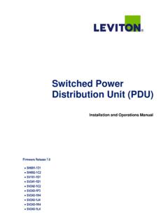
6 Secure each connector with electrical tape. WARNING: CONNECT AN ELECTRONIC LOW-VOLTAGE DIMMER ONLY TO THE PRIMARY (HIGH-VOLTAGE) SIDE OF A ELECTRONIC LOW-VOLTAGE TRANSFORMER. NOTE: Dimmer can be installed on either the Load or Line side. Green dimmer Ground lead to Green or bare copper wire in wall box. Black dimmer lead to tagged (common) wall box wire identified when removing old switch. White dimmer lead to White Neutral wall box wire. Remove Red insulating label from Red lead. Any Red dimmer lead to any of the remaining wall box wires. Remaining Red dimmer lead to remaining wall box wire. Testing your Dimmer prior to mounting in wall box: Dimmer Mounting: TURN OFF POWER AT CIRCUIT BREAKER OR FUSE.
7 Single -Pole Wiring Application using 3-Way Dimmer: Connect wires per WIRING DIAGRAM as follows: Screw wire nuts on clockwise making sure no bare conductors show below the wire connectors. Secure each connector with electrical tape. WARNING: CONNECT AN ELECTRONIC LOW-VOLTAGE DIMMER ONLY TO THE PRIMARY (HIGH-VOLTAGE) SIDE OF A ELECTRONIC LOW-VOLTAGE TRANSFORMER. Green dimmer Ground lead to Green or bare copper wire in wall box. Black dimmer lead to any wall box wire removed from old switch. White dimmer lead to White Neutral wall box wire. Red dimmer lead without insulating label to remaining wall box wire. Remaining Red dimmer lead should have Red insulation label affixed.
8 Proceed to Step 6. NOTE: If insulating label is not affixed to Red lead, use a small wire nut or electrical tape to cap off. Proceed to Step 6. 3-Way Wiring Application: LIMITED 5 YEAR WARRANTY AND EXCLUSIONSL eviton warrants to the original consumer purchaser and not for the benefit of anyone else that this product at the time of its sale by Leviton is free of defects in materials and workmanship under normal and proper use for five years from the purchase date. Leviton s only obligation is to correct such defects by repair or replacement, at its option, if within such five year period the product is returned prepaid, with proof of purchase date, and a description of the problem to Leviton Manufacturing Co., Inc., Att: Quality Assurance Department, 59-25 Little Neck Parkway, Little Neck, New York 11362-2591.
9 This warranty excludes and there is disclaimed liability for labor for removal of this product or reinstallation. This warranty is void if this product is installed improperly or in an improper environment, overloaded, misused, opened, abused, or altered in any manner, or is not used under normal operating conditions or not in accordance with any labels or instructions. There are no other or implied warranties of any kind, including merchantability and fitness for a particular purpose, but if any implied warranty is required by the applicable jurisdiction, the duration of any such implied warranty, including merchantability and fitness for a particular purpose, is limited to five years. Leviton is not liable for incidental, indirect, special, or consequential damages, including without limitation, damage to, or loss of use of, any equipment, lost sales or profits or delay or failure to perform this warranty obligation.
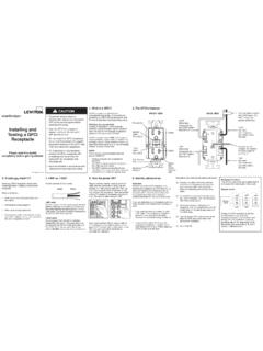
10 The remedies provided herein are the exclusive remedies under this warranty, whether based on contract, tort or otherwise. Restore power at circuit breaker or fuse. Carefully holding Dimmer as shown, slide control lever to highest postion. If lights are not ON, press rocker. Lights should turn ON to brightest level. If lights do not turn ON, refer to the TROUBLESHOOTING section. Step 5bBlackTagRedRedNeutralGroundGreenWhiteS tep 6 Step 7 Installation may now be completed by carefully positioning all wires to provide room in wall box for dimmer. Mount dimmer into box with mounting screws supplied. Attach Decora wallplate. Restore Power: Restore power at circuit breaker or fuse. Installation is NOTE: If using the dimmer in a 3-Way application, the lights will turn ON at the level the slider is set for both Single pole and 3-Way applications.