Transcription of SMPS MOSFET IRFP460A - irf.com
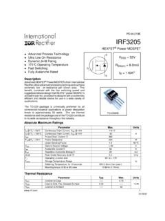
1 PD- 91880. SMPS MOSFET IRFP460A . HEXFET Power MOSFET . Applications l Switch Mode Power Supply ( SMPS ) VDSS Rds(on) max ID. l Uninterruptable Power Supply 500V 20A. l High speed power switching Benefits l Low Gate Charge Qg results in Simple Drive Requirement l Improved Gate, Avalanche and dynamic dv/dt Ruggedness l Fully Characterized Capacitance and Avalanche Voltage and Current TO-247AC G D S. l Effective Coss specified ( See AN1001). Absolute Maximum Ratings Parameter Max. Units ID @ TC = 25 C Continuous Drain Current, VGS @ 10V 20. ID @ TC = 100 C Continuous Drain Current, VGS @ 10V 13 A. IDM Pulsed Drain Current 80. PD @TC = 25 C Power Dissipation 280 W.
2 Linear Derating Factor W/ C. VGS Gate-to-Source Voltage 30 V. dv/dt Peak Diode Recovery dv/dt V/ns TJ Operating Junction and -55 to + 150. TSTG Storage Temperature Range C. Soldering Temperature, for 10 seconds 300 ( from case ). Mounting torqe, 6-32 or M3 screw 10 lbf in ( m). Typical SMPS Topologies: l Full Bridge l PFC Boost Notes through are on page 8. 1. 6/23/99. IRFP460A . Static @ TJ = 25 C (unless otherwise specified). Parameter Min. Typ. Max. Units Conditions V(BR)DSS Drain-to-Source Breakdown Voltage 500 V VGS = 0V, I D = 250 A. V(BR)DSS/ TJ Breakdown Voltage Temp. Coefficient V/ C Reference to 25 C, ID = 1mA. RDS(on) Static Drain-to-Source On-Resistance VGS = 10V, ID = 12A.
3 VGS(th) Gate Threshold Voltage V VDS = VGS , ID = 250 A. 25 VDS = 500V, VGS = 0V. IDSS Drain-to-Source Leakage Current A. 250 VDS = 400V, VGS = 0V, T J = 125 C. Gate-to-Source Forward Leakage 100 VGS = 30V. IGSS nA. Gate-to-Source Reverse Leakage -100 VGS = -30V. Dynamic @ TJ = 25 C (unless otherwise specified). Parameter Min. Typ. Max. Units Conditions gfs Forward Transconductance 11 S VDS = 50V, ID = 12A. Qg Total Gate Charge 105 ID = 20A. Qgs Gate-to-Source Charge 26 nC VDS = 400V. Qgd Gate-to-Drain ("Miller") Charge 42 VGS = 10V, See Fig. 6 and 13 . td(on) Turn-On Delay Time 18 VDD = 250V. tr Rise Time 55 ns ID = 20A. td(off) Turn-Off Delay Time 45 RG =.
4 Tf Fall Time 39 R D = 13 ,See Fig. 10 . Ciss Input Capacitance 3100 VGS = 0V. Coss Output Capacitance 480 VDS = 25V. Crss Reverse Transfer Capacitance 18 pF = , See Fig. 5. Coss Output Capacitance 4430 VGS = 0V, VDS = , = Coss Output Capacitance 130 VGS = 0V, VDS = 400V, = Coss eff. Effective Output Capacitance 140 VGS = 0V, VDS = 0V to 400V. Avalanche Characteristics Parameter Typ. Max. Units EAS Single Pulse Avalanche Energy 960 mJ. IAR Avalanche Current 20 A. EAR Repetitive Avalanche Energy 28 mJ. Thermal Resistance Parameter Typ. Max. Units R JC Junction-to-Case R CS Case-to-Sink, Flat, Greased Surface C/W. R JA Junction-to-Ambient 40. Diode Characteristics Parameter Min.
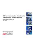
5 Typ. Max. Units Conditions D. IS Continuous Source Current MOSFET symbol 20. (Body Diode) showing the A. ISM Pulsed Source Current integral reverse G. 80. (Body Diode) p-n junction diode. S. VSD Diode Forward Voltage V TJ = 25 C, IS = 20A, VGS = 0V . trr Reverse Recovery Time 480 710 ns TJ = 25 C, IF = 20A. Qrr Reverse RecoveryCharge C di/dt = 100A/ s . ton Forward Turn-On Time Intrinsic turn-on time is negligible (turn-on is dominated by LS+LD). 2 IRFP460A . 100 100 VGS. VGS. TOP 15V TOP 15V. 10V 10V. I D , Drain-to-Source Current (A). I D , Drain-to-Source Current (A). BOTTOM BOTTOM 10. 10. 1. 20 s PULSE WIDTH 20 s PULSE WIDTH. TJ = 25 C TJ = 150 C. 1. 1 10 100 1 10 100.
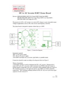
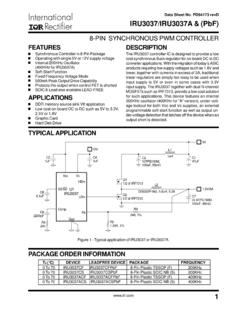
6 VDS , Drain-to-Source Voltage (V) VDS , Drain-to-Source Voltage (V). Fig 1. Typical Output Characteristics Fig 2. Typical Output Characteristics 100 20A. ID = 19A. RDS(on) , Drain-to-Source On Resistance I D , Drain-to-Source Current (A). TJ = 150 C. 10 (Normalized). TJ = 25 C. 1 V DS = 50V. 20 s PULSE WIDTH VGS = 10V. -60 -40 -20 0 20 40 60 80 100 120 140 160. VGS , Gate-to-Source Voltage (V) TJ , Junction Temperature ( C). Fig 3. Typical Transfer Characteristics Fig 4. Normalized On-Resistance Vs. Temperature 3. IRFP460A . 100000 20. V G S = 0V, f = 1M Hz ID = 19A. 20A. C is s = C g s + C g d , Cd s SHO RTED VDS = 400V. C rs s = C g d VGS , Gate-to-Source Voltage (V).
7 VDS = 250V. 10000 C oss = C ds + C gd 16 VDS = 100V. C, Capacitance (pF). C iss 1000 12. C o ss 100 8. C rss 10 4. FOR TEST CIRCUIT. SEE FIGURE 13. 1 A 0. 1 10 100 1000 0 20 40 60 80 100. V D S , D ra in-to-S ource V oltage (V) Q G , Total Gate Charge (nC). Fig 5. Typical Capacitance Vs. Fig 6. Typical Gate Charge Vs. Drain-to-Source Voltage Gate-to-Source Voltage 100 1000. OPERATION IN THIS AREA LIMITED. BY RDS(on). ISD , Reverse Drain Current (A). TJ = 150 C. I D , Drain Current (A). 10 100. 10us TJ = 25 C 100us 1 10. 1ms TC = 25 C. TJ = 150 C 10ms V GS = 0 V Single Pulse 1. 10 100 1000 10000. VSD ,Source-to-Drain Voltage (V) VDS , Drain-to-Source Voltage (V).
8 Fig 7. Typical Source-Drain Diode Fig 8. Maximum Safe Operating Area Forward Voltage 4 IRFP460A . 20 RD. VDS. VGS. 15. RG. +. I D , Drain Current (A). -VDD. 10V. Pulse Width 1 s 10. Duty Factor %. Fig 10a. Switching Time Test Circuit 5. VDS. 90%. 0. 25 50 75 100 125 150. TC , Case Temperature ( C). 10%. VGS. Fig 9. Maximum Drain Current Vs. td(on) tr t d(off) tf Case Temperature Fig 10b. Switching Time Waveforms 1. Thermal Response (Z thJC ). D = P DM. SINGLE PULSE. (THERMAL RESPONSE) t1. t2. Notes: 1. Duty factor D = t 1 / t 2. 2. Peak T J = P DM x Z thJC + TC. 1. t1 , Rectangular Pulse Duration (sec). Fig 11. Maximum Effective Transient Thermal Impedance, Junction-to-Case 5.
9 IRFP460A . 2400. 1 5V ID. EAS , Single Pulse Avalanche Energy (mJ). TOP 2000 13A. L D R IV E R BOTTOM 20A. VDS. 1600. RG D .U .T +. V. - DD. IA S A. 1200. 20V. tp 0 .0 1 . 800. Fig 12a. Unclamped Inductive Test Circuit V (B R )D SS. tp 400. 0. 25 50 75 100 125 150. Starting TJ , Junction Temperature( C). IAS. Fig 12c. Maximum Avalanche Energy Fig 12b. Unclamped Inductive Waveforms Vs. Drain Current QG. 10 V. 620. QGS QGD. V D S a v , A valanche V oltage (V ). VG. 600. Charge 580. Fig 13a. Basic Gate Charge Waveform Current Regulator Same Type as 50K 560. 12V .2 F..3 F. +. V. - DS. 540 A. 0 4 8 12 16 20. VGS. I av , A v alanche C urrent (A). 3mA. IG ID. Current Sampling Resistors Fig 12d.
10 Typical Drain-to-Source Voltage Fig 13b. Gate Charge Test Circuit Vs. Avalanche Current 6 IRFP460A . Peak Diode Recovery dv/dt Test Circuit + Circuit Layout Considerations Low Stray Inductance Ground Plane . Low Leakage Inductance Current Transformer - +.. - +. - . RG dv/dt controlled by RG +. Driver same type as VDD. - ISD controlled by Duty Factor "D". - Device Under Test Driver Gate Drive Period D=. Period VGS=10V *. ISD Waveform Reverse Recovery Body Diode Forward Current Current di/dt VDS Waveform Diode Recovery dv/dt VDD. Re-Applied Voltage Body Diode Forward Drop Inductor Curent Ripple 5% ISD. * VGS = 5V for Logic Level Devices Fig 14. For N-Channel HEXFETS.