Example: stock market
Solid State Relays Common Precautions
The internal snubber circuit is charged and will cause electric shock. Do not touch the SSR load terminal immediately after the power is turned OFF. ... As an absorption element, the diode is the most effective at suppressing the counter-electromotive force. The release time for the solenoid or electromagnetic valve will, however, increase.
Tags:
Information
Domain:
Source:
Link to this page:
Documents from same domain

CSM PCB Con CN J 1 3 - omronfs.omron.com
omronfs.omron.comA-20 最新の商品情報・便利な情報は www.fa.omron.co.jp/ コネクタ 共通の注意事項 コネクタ 共通の注意事項 挿抜作業について ・通電中の挿抜作業時および抜去後に、コネクタの接点 …

CSM XM2 XM3 AC DS J 1 8 - omronfs.omron.com
omronfs.omron.com2 最新の商品情報・便利な情報は www.fa.omron.co.jp/ XM2/XM3 Dサブコネクタ X M 2 / X M 3 注1. 1個のコネクタに固定具は2個必要です。 注2. 形XM3K/Lには取付できません。

Solid State Pressure Sensors D8M - omronfs.omron.com
omronfs.omron.comCompact D8M solid state pressure sensors provide reliable detection for gas and air inflow for burner controls in water heaters, furnaces and other gas-fired devices.
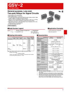
G5V-2 - omronfs.omron.com
omronfs.omron.com2 G5V-2 Low Signal Relay G 5 V-2 Ratings Coil Note 1. The rated current and coil resistance are measured at a coil temperature of 23°C with a tolerance of ±10%. 2.Operating characteristics are measured at a coil temperature of 23°C.

G6B - Omron
omronfs.omron.com3 G6B PCB Power Relay G 6 B Models for Ultrasonically Cleanable Note: When ordering, add the rated coil voltage to the model number. Example: G6B-1114P-US DC5 However, the notation of the coil voltage on the produc t case as well as on the packing will be marked as @@ VDC.

DC Power Relays
omronfs.omron.comHigh-voltage, High-current Loads • A compact relay (73 x 36 x 67.2 mm (L x W x H)) capable of switching 400-V 60-A DC loads. (Capable of interrupting 600 A at 300 VDC max.) • The switching section and driving section are gas-injected and hermetically sealed, allowing these compact relays to interrupt high-capacity loads.

G7L - Omron
omronfs.omron.com• Miniature size for maximum switching power, particularly for inductive loads. • Flame-resistance materials (UL94V-0-qualifying) used for all insulation material. • Quick-connect, screw, and PCB terminals, and DIN track mounting available. • Conforms to UL, CSA, TUV and meets IEC950. • Safety design with contact gap of 3 mm.

G2RL - Omron
omronfs.omron.comTest conditions: Shock is applied in ±X, ±Y, and ±Z directions three times each with without energizing the relays to check the number of malfunctions. Requirement: None malfuction 100 m/s2 Sample: G2RL-24 12 VDC Number of relays: 5 pcs Test conditions: Shock is applied in ±X, ±Y, and ±Z directions three times each with without energizing

G6S - Omron
omronfs.omron.comElectrical 100,000 operations min. for AC (at 1,800 operations/h with rated load) 100,000 operations min. for DC (at 1,200 operations/h with rated load) Failure rate (P level) (reference value) *3 10 μA at 10 m VDC Ambient operating temperature-40°C to 85°C (with no icing or condensation), and -40°C to 70°C (with no icing or condensation)

G2R - Omron
omronfs.omron.com3 G2R PCB Power Relay G 2 R Quick-connect Terminal (#187) Full-wave Rectifier For Ultrasonically Cleanable Note: When ordering, add the rated coil voltage to the model number. Example: G2R-1A-T AC12 However, the notation of the coil voltage on the produc t case as well as on the packing will be marked as @@ VAC.
Related documents
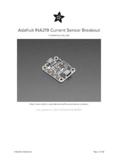
Adafruit INA219 Current Sensor Breakout
cdn-learn.adafruit.comNov 15, 2021 · snubber diode to protect against inductive spikes. • • • ©Adafruit Industries Page 13 of 28. Arduino Code Programming the Adafruit INA219 breakout board is simple using our library: Install the Library Open up the Arduino library …

AN5028 Application note - STMicroelectronics
www.st.comswitching diode and power losses in the snubber resistor due to the diode) Switching power losses generated by the reverse recovery current of an ultrafast diode in a switching cell (diode + MOSFET or IGBT) The diodes discussed are all STMicroelectronics ultrafast diodes from …

Snubber circuit design methods - Rohm
fscdn.rohm.comMOSFET bridge; (b) RC snubber where the resistor R SNB and capacitor C SNB are connected in parallel to each MOSFET; (c) Discharge RCD snubber, where a diode is added to RC snubber; and (d) non-discharge RCD snubber, where the discharging path is changed from the discharge RCD snubber presented in (c). -10 0 10 20 30 40 50 60-200 0 200 400 600 800

Flyback Converter - SysCon
www.sc.iitb.ac.inFigure 13 represents the snubber circuit on the primary side of transformer to prevent voltage spike, during transition of states. Use of zener clamp and parallel RC optimizes both EMI and energy efficiency. Figure 13: Snubber circuit for primary winding Remaining subpart of the schematic represents a DC-DC flyback converter topology as shown

Transformerdesignconsideration forFull Bridge PhaseShift
www.psma.comMar 17, 2020 · PAGE 30 L LK Inductance A lot of models can be found in literature for calculating the leakage inductance. Two of them are: CLASSICAL MODEL: This is a simple method for calculating the leakage inductance since only a small number of dimensions are necessary related to the winding geometry.
DC/AC Pure Sine Wave Inverter
web.wpi.eduIntroduction This report focuses on DC to AC power inverters, which aim to efficiently transform a DC power source to a high voltage AC source, similar to power that would be available at an electrical wall outlet.