Transcription of ST SPI protocol
1 September 2013 Doc ID 023176 Rev 21/28TN0897 Technical noteST SPI protocolIntroductionThe document describes a standardized SPI protocol . It defines a common structure of the communication frames and defines specific addresses for product and status ID 023176 Rev 2 Contents1 General description .. list .. description .. 62 SPI communication flow .. description .. byte .. code definition .. status register .. error flag definition .. register (optional) .. 133 Address mapping .. address range .. address range .. 154 Write operation .. command format .. of data shifted out at SDO during write cycle .. 185 Read operation .. command format .. of data shifted out at SDO during Read cycle .. 206 Read and clear status operation .. and clear status command format .. of data shifted out at SDO during read and clear status operation 227 Read device information.
2 Version .. code .. 24TN0897 ContentsDoc ID 023176 Rev 23/28 Appendix A Reference documents.. 25 Appendix B Product code .. 26 Revision history .. 27 List of tablesTN08974/28 Doc ID 023176 Rev 2 List of tablesTable byte (8 bit) .. 10 Table code definition .. 10 Table Status Register .. 11 Table of Global Status bits .. 11 Table register .. 14 Table operation code .. 15 Table address range .. 15 Table operation code.. 15 Table address range .. 16 Table information .. 23 Table .. 23 Table family .. 23 Table version.. 24 Table version coding .. 24 Table .. 24 Table width .. 24 Table code.. 26 Table revision history .. 27TN0897 List of figuresDoc ID 023176 Rev 25/28 List of figuresFigure SPI signal description .. 7 Figure signal description .. 7 Figure principle of the ST SPI.
3 9 Figure error flag definition.. 13 Figure command format .. 17 Figure Frame composition during WRITE operation .. 18 Figure operation - 16 bit frame .. 18 Figure command format .. 19 Figure Frame composition during READ operation.. 20 Figure operation - 16 bit frame .. 20 Figure and clear status command format .. 21 Figure Frame composition during READ and CLEAR operation.. 22 Figure and clear status operation - 16 bit frame.. 22 General descriptionTN08976/28 Doc ID 023176 Rev 21 General Feature list Standardized communication frame structure Variable frame width Global status information available in every communication frame In-frame response Pre-defined address assignment Fail-safe concept Robust communication protocol Bus fault detection Global failure Indication Product information Product name and family Silicon version Plug & play concept (standardized access to product information) Signal descriptionSerial Clock (SCK): this input signal provides the timing of the serial interface.
4 Data present at Serial Data Input (SDI) is latched on the rising edge of Serial Clock (SCK). Data on Serial Data Out (SDO) is shifted out at the falling edge of Serial Clock (SCK). Serial Data Input (SDI): this input is used to transfer data serially into the device. It receives the data to be written. Values are latched on the rising edge of Serial Clock (SCK).Serial Data Output (SDO): this output signal is used to transfer data serially out of the device. Data is shifted out on the falling edge of Serial Clock (SCK).SDO also reflects the status of the <Global Error Flag> (Bit 7 of the <Global Status Register>) while CSN is low and no clock signal is presentChip Select Not (CSN): when this input signal is High, the device is not selected and Serial Data Output (SDO) is high impedance. Driving this input Low enables the communication . The communication must start and stop on a Low level of Serial Clock (SCK).
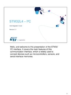
5 Failure Status (FSTAT) (optional): the <FSTAT> pin reflects the status of the <Global Error Flag> (Bit 7 of the <Global Status Register>). It is an open-drain output signal so that <FSTAT> pins of several devices can be connected to a common pull-up resistor and one microcontroller I/O port in order to indicate a failure in the descriptionDoc ID 023176 Rev 27/28 Figure SPI signal descriptionThe SPI can be driven by a microcontroller with its SPI peripheral running in following mode: CPOL = 0 and CPHA = signal descriptionThe communication starts at the CSN transition from High to Low. SCK is initially at SDI must be stable at the first SCK transition from Low to at SDO is shifted at the first falling edge of transition Low to High must occur after the specified number of clock cycles (rising and falling edges of SCK are counted).
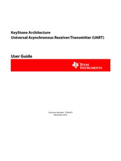
6 SCKSDISDOCSNFSTAT optional &616&. 6',6'206%06%/6%/6%*$3*&)7 &32/ &3+$ +,+,SPI communication flowTN08978/28 Doc ID 023176 Rev 22 SPI communication General descriptionThe proposed SPI communication is based on a standard SPI interface structure using CSN (Chip Select Not), SDI (Serial Data In), SDO (Serial Data Out/Error) and SCK (Serial Clock) signal lines. At device start-up the master reads the <SPI-frame-ID> register (ROM address 3EH) of the slave device. This 8-bit register indicates the SPI frame length (16, 24, or 32 bit) and the availability of additional communication frame consists of an instruction byte which is followed by 1, 2 or 3 data data returned on SDO within the same frame always starts with the <Global Status> register. It provides general status information about the device.
7 It is followed by 1, 2 or 3 data bytes (i. e. In-frame-response ).For write cycles the <Global Status> register is followed by the previous content of the addressed read cycles the <Global Status> register is followed by the content of the addressed communication flowDoc ID 023176 Rev 29/28 Figure principle of the ST Command byteEach communication frame starts with a command byte. It consists of an operating code which specifies the type of operation (<Write>, <Read>, <Read and Clear>, <Read Device Information>) and a 6 bit address. If less than 6 address bits are required, the remaining bits are unused but are '26',06%06%/6%/6%:ULWH2 SHUDWLRQ&616'26',*OREDO 6 WDWXV%\WH ELW 06%06%/6%/6%'DWD 5 HDG 2 SHUDWLRQ06%/6%06%/6% RU ELW &RPPDQG%\WH ELW *OREDO 6 WDWXV%\WH ELW &RPPDQG%\WH ELW 'RQ W FDUH RU ELW 'DWD SUHYLRXV FRQWHQW RI UHJLVWHU 'DWD RU ELW *$3*&)7 SPI communication flowTN089710/28 Doc ID 023176 Rev 2 OCx: operating codeAx: Operating code definition The <Write Mode>, <Read Mode> and <Read and Clear Status> operations allow access to the RAM of the device, i.
8 E. to write to control registers or read status information.<Read Device Information> allows access to the ROM area which contains device related information such as the product family, product name, silicon version, register width and availability of a 1 For 16-bit framesCommand Byte: 0000 1000 Data Byte: 1111 1111 Write FFH at RAM address 08 HExample 2 For 16-bit framesCommand Byte: 0111 1110 Data Byte: 0000 0000 Read register at RAM address 3 EHExample 3 For 16-bit framesCommand Byte: 1011 1110 Data Byte: 0000 0000 Read register at RAM address 3EH and clear its content at CSN low to high transitionTable byte (8 bit)Operating codeAddressMSBLSBOC1OC0A5A4A3A2A1A0 Table code definitionOC1OC0 Meaning00<Write mode>01<Read mode>10<Read and clear status>11<Read device information>TN0897 SPI communication flowDoc ID 023176 Rev 211/28 Example 4 For 16-bit framesCommand Byte: 1111 1110 Data Byte.
9 0000 0000 Read register at ROM address 3EH (i. e. <SPI-frame-ID>) Global status register Table Status RegisterBit 7 Bit 6 Bit 5 Bit 4 Bit 3 Bit 2 Bit 1 Bit 0 Global Error Flag (GEF)Comm ErrorNot (Chip Reset OR Comm Error) TSD / chip overloadTframe / Temp prewarningDevice specificDevice specificFail SafeTable of Global Status bitsBitDescriptionOptionalfeaturePolarit yComment0 Fail SafeXActive highIndicates that the device is in Fail Safe Mode (1). The bit is defined as 0 if no fail-safe functionality is present in the device1. Fail-safe Mode is an operating mode where the device enters a safe state. The precise definition is device specific and is defined in the product specificXActive high See product datasheet(2)2. See Appendix A: Reference specificXActive high See product datasheet(2)3 Temp pre-warningXActive highThe bit is defined as 0 if feature is not present.
10 See product datasheet4 Thermal Shutdown / Chip OverloadXActive highThe bit is defined as 0 if feature is not present. See product datasheet5 Not (Chip Reset OR communication Error)Active lowChip Reset: registers have been set to default communication Error: see bit 6 The bit is cleared automatically after a valid communication with any registerAfter Power-On the bit is 0 and is set to 1 by a valid SPI communication6 communication ErrorActive highBit is set if the number of clock cycles during CSN = low does not match with the specified frame width or if any other device specific communication error occurs. See product datasheet(2)7 Global Error Flag (GEF)Active highLogic OR combination of all failures in the <Global Status register> and additional device specific failuresSPI communication flowTN089712/28 Doc ID 023176 Rev Global error flag definitionThe <Global Error Flag> (GEF) is a diagnosis information which is transmitted with every communication frame.