Transcription of Strengthening of a Long Span Prestressed Segmental Box ...
1 Strengthening of a Long Span Prestressed Segmental box girder bridge Bruno Massicotte , Associate Professor Department of Civil Engineering Ecole Polytechnique de Montreal Montreal, Quebec, Canada Formerly, bridge Design Engineer at the Quebec Ministry of Transportation Andre Picard , Professor Department of Civil Engineering Universite Laval Quebec City, Quebec, Canada Yvon Gaumond, bridge Design Chief Engineer bridge Department Quebec Ministry of Transportation Quebec City, Quebec, Canada Claude Ouellet, Senior bridge Engineer bridge Department Quebec Ministry of Transportation Quebec City, Quebec, Canada 52 The Grand-Mere bridge in the province of Quebec, Canada, is a 285 m (935 ft) long, cast-in-place, Segmental box girder bridge that experienced several problems which resulted in distress characterized by an increasing de-flection combined with localized cracking.
2 These defects were due mainly to insufficient prestressing causing high tensile stresses in the deck and possible corrosion of the pre-stressing steel. To remedy this situation, the Quebec Ministry of Transportation strength-ened the bridge by adding external prestress-ing equivalent to 30 percent of the remaining internal prestressing. The paper describes the causes of the distress and focuses on the as-sumptions adopted in the analyses to deter-mine the current state of the bridge . The tech-nique and design criteria used in Strengthening the Grand-Mere bridge are described. Also, the construction aspects and the various prob-lems met during the external prestressing op-eration are discussed. The new technology and experience gained in Strengthening this structure can be applied to both pretensioned and post-tensioned concrete bridges.
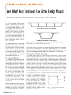
3 The Grand-Mere Bri dge, a 285 m (935 ft) long, cast-in-place, post-tensioned Segmental structure built i n 1977 (Fig. 1), consists of a single-cell box girder . It is located 200 km (125 miles) northeast of Montreal on High-way 55, where it crosses the St. Maurice R iver near the town of Grand- Mere. PCI JOURNAL An article on the design and con-struction of the Grand-Mere bridge appeared in the January-February 1979 PCI JOURNAV and the project won a Special Jury Award in the 1978 PCI Awards Program. This long and slender bridge is an elegant structure which blends in well with the sur-rounding landscape. Unfortunately, this bridge experi-enced various problems and distress during and after its construction, result-ing in localized cracking and increasing deflection in the m (595 ft) cen-tral span.
4 These problems were due mainly to insufficient prestressing as a result of construction problems, opti-mistic design assumptions, and a lim-ited state of knowledge at that time, es-pecially regarding thermal stresses. Numerous studies showed that the short-term bridge safety was adequate. However, because of the potential risk of cracking in the deck, the studies also indicated that the long-term in-tegrity could be affected if corrective measures were not taken immediately. Based on these technical evaluations and considering the structure's impor-tance, the owner, the Quebec Ministry of Transportation (QMT), decided to strengthen the bridge . Additional lon-gitudinal prestressing corresponding to 30 percent of the remaining amount corrected the lack of sufficient pre-stressing.
5 The Strengthening design, in which the authors of this paper played an active role, was done by the QMT bridge Department. Construction began in May 1991 and the additional prestressing was fi-nally applied to the bridge in Novem-ber of the same year. The technology used in the Strengthening of the bridge can be applied to all Prestressed con-crete structures, whether pretensioned or post-tensioned. Exterior pier Fi g. 1. The Grand-Mere bridge . SCOPE OF THE PAPER This paper is the first of two com-panion papers describing the correc-tive measures applied to the Grand-Mere bridge . The scope of this first paper is to present the history of the bridge , describe the various problems met during construction, and discuss the subsequent distresses, their causes and their remedies.
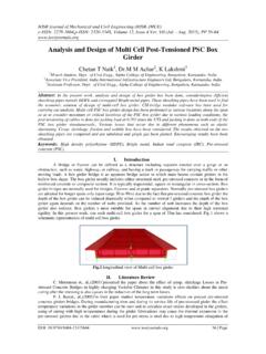
6 It presents the as-sumptions used in the analyses to es-tablish the bridge state and later to de-sign the Strengthening program. The use of individually lubricated strands and details of the cable anchorage sys-tem to the existing structure are de-scribed. The construction aspects and problems faced during the strengthen-ing process are also discussed. The paper deals with practical considera-tions and is addressed to bridge engi-neers who may face similar problems. The companion paper/ on the other hand, presents the details of an impor-Fi g. 2. Longitudinal elevation of the Grand-Mere bridge . May-June 1994 tant monitoring program carried out on the bridge during the Strengthening process. This program studied the var-ious aspects of the bridge 's behavior before, during and after the strength-ening operation.
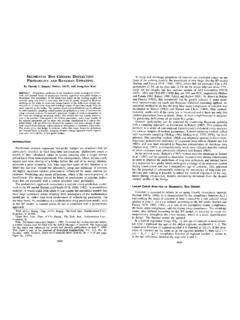
7 bridge DESCRIPTION The Grand-Mere bridge , a 285 m (935 ft) long structure, consists of three continuous spans of , and m (130, 595 and 130ft), completed with a wedge-shaped, solid cantilever of m (40ft) at each end acting as counterweights (Fig. 2) . The length of the central span was a re-markable achievement in 1977, and is still among the longest for this kind of bridge in North America. T~e bridge is an elegant, slender structure span-ning the St. Maurice River. In the central span, the depth of the box girder varies parabolically from m (32 ft) at the piers to m [m] 1 m = ft 53 r4 ----12 800--------+1:1 142060 ~ .. ,,l, .. , .. , .. , ., .. , ., .. ,. , .. , .. , '\~/", .. ~ :~~ {61 0 end spans :i:~ ::::::: 356 central span ::::::: 0 LO.}
8 0) ~~~~~ ~ ~~.i 152 --~ [mm) ; ~ fFJ!!:{~/'t/Ji 1000 mm =1m 1 m = ln. = ft 11) Cross section Ill the interior piers [mm] b) Cross section at midspan Fig. 3. Cross sections of the Grand-Mere bridge at interior piers and midspan. ( ft) at midspan (Fig. 3), giving span-to-depth ratios of and , respectively. The depth of the box girder in the end spans varies slightly, from m (32ft) at the interior piers to m (28 ft) at the exterior piers. The total width of the deck is m (42 ft), including a m (22 ft) wide top flange of the single-cell box girder and two m (10 ft) cantilevers. This torsionally stiff box girder bridge h as only m (6 ft) thick di-aphragms over the main piers. The designer planned to place 930 m3 (1216 cu yd) of gravel ballast in the chambers of both end spans.]}
9 The bal-lasted chambers and the wedge-shaped, solid cantilevers would co unterbalance the weight of the main span during the cantilever co nstruction an d avoid any uplift of the box girder at the ex terior 54 piers as a consequence of the unusual center-to-end span ratio of Construction and Materials The bridge construction lasted two years, from 1976 to 1977, interrupted during the winter season to avoid cold weather concreting. The end spans were erected the first year and were cast on scaffolding. The central span was built i n 1977, using the progres-sive cantilever method with traveling forms for the cast-in-place segments. After construction of the two segmen-tal cantilevers of the central span, a keystone segment was cast and th e continuity prestressing in the bot tom flange and webs was added.
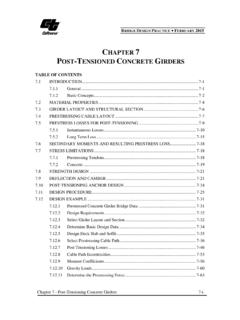
10 Gravel ballast in the end spans was applied progressively, in three stages, as the cantilever construction proceeded. The box girder was Prestressed using 32 mrn ( in.) diameter pre-stressing bars with 1030 MPa (150 ksi) ultimate stress. The bridge was Prestressed longitudinally during the cantilever construction with 284 straight bars located in the upper deck. The continuity prestressing comprises 80 slightly curved bars in the bottom flange and 48 draped bars in the webs (Fig. 4). Shear reinforcement consists of straight prestressing bars, either verti-cal or inclined, and of conventional mild reinforcing steel. The deck is pre-stressed transversely with straight bars. Moreover, passive reinforcement of each segment was extended through adjacent segment joints.