Transcription of Surface Mount Multilayer Ceramic Chip Capacitors (SMD ...
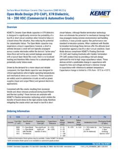
1 KEMET Electronics Corporation Box 5928 Greenville, SC 29606 864-963-6300 C1010_X7R_HV_SMD 2/23/20181 One world. One KEMETO verviewKEMET s High Voltage Surface Mount MLCCs in X7R dielectric feature a 125 C maximum operating temperature and are considered temperature stable. The Electronics Industries Alliance (EIA) characterizes X7R dielectric as a Class II material. Components of this classification are fixed, Ceramic dielectric Capacitors suited for bypass and decoupling applications or for frequency discriminating circuits where Q and stability of capacitance characteristics are not critical. X7R exhibits a predictable change in capacitance with respect to time and voltage and boasts a minimal change in capacitance with reference to ambient temperature.
2 Capacitance change is limited to 15% from 55 C to +125 C. Available in a variety of case sizes and industry leading CV values (capacitance/voltage), these devices exhibit low leakage current and low ESR at high frequencies. Conventional uses include both snubbers and filters in applications such as switching power supplies and lighting ballasts. Their exceptional performance at high frequencies has made high voltage MLCC's the preferred dielectric choice of design engineers worldwide. In addition to their use in power supplies, these Capacitors are widely used in industries related to automotive (hybrid), telecommunications, medical, military, aerospace, semiconductors and test/diagnostic addition to Commercial Grade, Automotive Grade devices are available which meet the demanding Automotive Electronics Council's AEC-Q200 qualification Mount Multilayer Ceramic chip Capacitors (SMD MLCCs)High Voltage X7R dielectric , 500 3,000 VDC(Commercial Grade)Ordering InformationC1210C154 KCRACTUC eramicCase Size (L" x W")Specification/SeriesCapacitance Code (pF)Capacitance ToleranceRated Voltage (VDC)
3 DielectricFailure Rate/DesignTermination Finish1 Packaging/ Grade (C-Spec)06030805120612101808181218252220 2225C = StandardTwo significant digits + number of = 5%K = 10%M = 20%C = 500 B = 630 D = 1,000 F = 1,500 G = 2,000 Z = 2,500 H = 3,000 R = X7RA = N/AC = 100% Matte SnL = SnPb (5% Pb minimum)See "Packaging C-Spec Ordering Options Table"below1 Additional termination finish options may be available. Contact KEMET for details. KEMET Electronics Corporation Box 5928 Greenville, SC 29606 864-963-6300 C1010_X7R_HV_SMD 2/23/20182 Surface Mount Multilayer Ceramic chip Capacitors , (SMD MLCCs)High Voltage X7R dielectric , 500 3,000 VDC (Commercial Grade)Packaging C-Spec Ordering Options TablePackaging Type1 Packaging/Grade Ordering Code (C-Spec)Bulk Bag/UnmarkedNot required (Blank)7" Reel/UnmarkedTU13" Reel/Unmarked7411 (EIA 0603 and smaller case sizes)7210 (EIA 0805 and larger case sizes)7" Reel/MarkedTM13" Reel/Marked7040 (EIA 0603 and smaller case sizes)7215 (EIA 0805 and larger case sizes)
4 7" Reel/Unmarked/2mm pitch2708113" Reel/Unmarked/2mm pitch270821 Default packaging is "Bulk Bag". An ordering code C-Spec is not required for "Bulk Bag" The terms "Marked" and "Unmarked" pertain to laser marking option of Capacitors . All packaging options labeled as "Unmarked" will contain Capacitors that have not been laser marked. Please contact KEMET if you require a laser marked option. For more information see "Capacitor Marking".2 The 2 mm pitch option allows for double the packaging quantity of Capacitors on a given reel size. This option is limited to EIA 0603 (1608 metric) case size devices. For more information regarding 2 mm pitch option see "Tape & Reel Packaging Information".
5 Benefits 55 C to +125 C operating temperature range Industry-leading CV values Exceptional performance at high frequencies Lead (Pb)-free, RoHS and REACH compliant EIA 0603, 0805, 1206, 1210, 1808, 1812, 1825, 2220, and 2225 case sizes DC voltage ratings of 500 V, 630 V, 1 KV, KV, 2 KV, KV, and 3 KV Capacitance offerings ranging from 10 pF to 560 nF Available capacitance tolerances of 5%, 10%, and 20% Low ESR and ESL Non-polar device, minimizing installation concerns Automotive (AEC Q200) Grade available 100% pure matte tin-plated termination finish allowing for excellent solderability SnPb plated termination finish option available upon request (5% Pb minimum)ApplicationsTypical applications include switch mode power supplies (input filters, resonators, tank circuits, snubber circuits, output filters), high voltage coupling and DC blocking, lighting ballasts, voltage multiplier circuits, DC/DC converters and coupling Capacitors in uk converters.
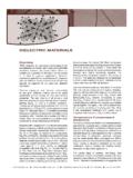
6 Markets include power supply, LCD fluorescent backlight ballasts, HID lighting, telecom equipment, industrial and medical equipment/control, LAN/WAN interface, analog and digital modems, and automotive (electric and hybrid vehicles, charging stations and lighting applications).Application NoteX7R dielectric is not recommended for AC line filtering or pulse applications. These Capacitors and/or the assembled circuit board containing these Capacitors may require a protective Surface coating to prevent external Surface arcing. KEMET Electronics Corporation Box 5928 Greenville, SC 29606 864-963-6300 C1010_X7R_HV_SMD 2/23/20183 Surface Mount Multilayer Ceramic chip Capacitors , (SMD MLCCs)High Voltage X7R dielectric , 500 3,000 VDC (Commercial Grade)Dimensions Millimeters (Inches) L B W STEIA Size CodeMetric Size CodeL LengthW WidthT ThicknessB BandwidthSSeparation MinimumMounting ( ) ( ) ( ) ( )See Table 2 for ( ) ( ) ( )Solder Wave or Solder ( ) ( ) ( ) ( ) ( ) ( ) ( ) ( ) ( ) ( ) ( ) ( ) ( ) ( ) ( ) ( ) ( ) ( ) ( )Solder Reflow ( ) ( ) ( ) ( ) ( ) ( )181245324.
7 5 0 ( 7 ) ( ) ( ) ( ) ( ) ( )182545644 .5 0 ( 7 ) ( ) ( ) ( ) ( ) ( ) ( ) ( )5 .0 0 ( 7 ) ( ) ( ) ( ) ( ) ( ) ( ) ( ) ( ) ( )Qualification/CertificationCommercial Grade products are subject to internal qualification. Details regarding test methods and conditions are referenced in Table 4, Performance & ComplianceLead (Pb)-free, RoHS, and REACH compliant without exemptions (excluding SnPb termination finish option). KEMET Electronics Corporation Box 5928 Greenville, SC 29606 864-963-6300 C1010_X7R_HV_SMD 2/23/20184 Surface Mount Multilayer Ceramic chip Capacitors , (SMD MLCCs)High Voltage X7R dielectric , 500 3,000 VDC (Commercial Grade)Electrical Parameters/CharacteristicsItemParameters /CharacteristicsOperating Temperature Range 55 C to +125 C Capacitance Change with Reference to +25 C and 0 Vdc Applied (TCC) 15% 1 Aging Rate (Maximum % Capacitance Loss/Decade Hour) Withstanding Voltage (DWV)150% of rated voltage for voltage rating of < 1000V 120% of rated voltage for voltage rating of 1000V (5 1 seconds and charge/discharge not exceeding 50mA)
8 3 Dissipation Factor (DF) Maximum Limit at 25 Resistance (IR) Minimum Limit at 25 CSee Insulation Resistance Limit Table (500 VDC applied for 120 5 secs at 25 C)1 Regarding Aging Rate: Capacitance measurements (including tolerance) are indexed to a referee time of 1,000 hours. 2 DWV is the voltage a capacitor can withstand (survive) for a short period of time. It exceeds the nominal and continuous working voltage of the Capacitance and dissipation factor (DF) measured under the following conditions: 1kHz 50Hz and Vrms if capacitance 10 F 120Hz 10Hz and Vrms if capacitance >10 F4 To obtain IR limit, divide M - F value by the capacitance and compare to G limit.
9 Select the lower of the two : When measuring capacitance it is important to ensure the set voltage level is held constant. The HP4284 & Agilent E4980 have a feature known as Automatic Level Control (ALC). The ALC feature should be switched to "ON". Post Environmental LimitsHigh Temperature Life, Biased Humidity, Moisture ResistanceDielectricRated DCVoltageCapacitanceValueDissipation Factor (Maximum %) CapacitanceShift Insulation ResistanceX7R> 20%10% of Initial Limit16 < Resistance Limit Table (X7R dielectric )EIA Case Size1,000 Megohm Microfarads or 100 G 100 Megohm Microfarads or 10 G 0603N/AAll0805< .0039 F .0039 F1206< F F1210< F F1808< F F1812< F F1825< uF uF2220< uF uF2225< uF uF KEMET Electronics Corporation Box 5928 Greenville, SC 29606 864-963-6300 C1010_X7R_HV_SMD 2/23/20185 Surface Mount Multilayer Ceramic chip Capacitors , (SMD MLCCs)High Voltage X7R dielectric , 500 3,000 VDC (Commercial Grade)Table 1A Capacitance Range/Selection Waterfall (0603 1812 Case Sizes)KEMET reserves the right to substitute product with an improved temperature characteristic, tighter capacitance tolerance and/or higher voltage capability within the same form factor (configuration and dimensions).
10 CapCap CodeCase Size/ SeriesC0603CC0805CC1206CC1210CC1808CC181 2 CVoltage CodeCBDCBDCBDFGCBDFGCBDFGZHCBDFGZHR ated Voltage (VDC)50063010005006301000500630100015002 0005006301000150020005006301000150020002 500300050063010001500200025003000 Capacitance ToleranceProduct Availability and chip Thickness Codes - See Table 2 for chip Thickness Dimensions10 pF100 JKMDG DG DGED ED ED ED EDFM FM FM FM FMLB LB LB LB LB LB LBGK GK GK GK GK GK GK11 pF110 JKMDG DG DGED ED ED ED EDFM FM FM FM FMLB LB LB LB LB LB LBGK GK GK GK GK GK GK12 pF120 JKMDG DG DGED ED ED ED EDFM FM FM FM FMLB LB LB LB LB LB LBGK GK GK GK GK GK GK13 pF130 JKMDG