Transcription of Switching Regulator Fundamentals (Rev. A)
1 1 SNVA559A September2012 RevisedSeptember2016 SubmitDocumentationFeedbackCopyright 2012 2016,TexasInstrumentsIncorporatedSwitchi ngRegulatorFundamentalsSIMPLESWITCHERis a registeredtrademarkof othertrademarksare the propertyof September2012 RevisedSeptember2016 SwitchingRegulatorFundamentalsABSTRACTT heswitchingregulatoris increasingin popularitybecauseit offersthe advantagesof higherpowerconversionefficiencyand increaseddesignflexibility(multipleoutpu tvoltagesof differentpolaritiescan begeneratedfroma singleinputvoltage).This paperwill detailthe operatingprinciplesof the four mostcommonlyusedswitchingconvertertypes: Buck usedto reducea DC voltageto a lowerDC providesan outputvoltagethat is higherthanthe (invert) an outputvoltagethat is generatedoppositein polarityto the an outputvoltagethat is less thanor greaterthanthe inputcan be generated,as well ,somemultiple-transistorconvertertopolog ieswill be presented.
2 Push-Pull A two-transistorconverterthat is especiallyefficientat low A two-transistorconverterusedin A four-transistorconverter(usuallyusedin offlinedesigns)that can generatethe highestoutputpowerof all the be providedalongwithcircuitexamplesthat illustratesomeapplicationsofBuck,Boost,a nd (t)+-vi(t)di/dt = 0v= 0 ITi(t)di/dt > 0v > 0 ITi(t)di/dt < 0v< September2012 RevisedSeptember2016 SubmitDocumentationFeedbackCopyright 2012 2016,TexasInstrumentsIncorporatedSwitchi ngRegulatorFundamentals1 SwitchingFundamentalsBeforebeginningexpl anationsof convertertheory,somebasicelementsof powerconversionwill Lawof InductanceIf a voltageis forcedacrossan inductor,a currentwill flow throughthat inductor(andthis currentwill varywith time).NOTE:The currentflowingin an inductorwill be time-varyingevenif the forcingvoltageis is equallycorrectto say that if a time-varyingcurrentis forcedto flow in an inductor,a voltageacrossthe inductorwill fundamentallaw that definesthe relationshipbetweenthe voltageand currentin an inductoris givenby Equation1:v = L (di/dt)(1)Two importantcharacteristicsof an inductorthat followdirectlyfromthe law of inductanceare:1.
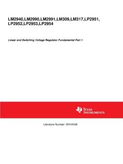
3 A voltageacrossan inductorresultsonly froma currentthat changeswith steady(DC)currentflowingin an inductorcausesno voltageacrossit (exceptfor the tiny voltagedropacrossthe copperusedin the windings).2. A currentflowingin an inductorcan not changevalueinstantly(in zerotime),as this wouldrequireinfinitevoltageto forceit to ,the fasterthe currentis changedin an inductor,thelargerthe resultingvoltagewill :Unlikethe currentflowingin the inductor,the voltageacrossit can changeinstantly(in zerotime).The principlesof inductanceare illustratedby the informationcontainedin InductorVoltage/CurrentRelationshipThe importantparameteris the di/dt term,whichis simplya measureof how the currentis plottedversustime,the valueof di/dt is definedas the slopeof the currentplotat any graphon the left showsthat currentwhichis constantwith time has a di/dt valueof zero,and resultsin no voltageacrossthe centergraphshowsthat a currentwhichis increasingwith time has a positivedi/dt value,resultingina CLOSED12V(N2 >>> N1)
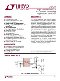
4 SPARKGAPSTORING ENERGYPOINTS OPEN12 VSPARK FIRESVPVSCCCURRENTLIMITINGRESISTORCOILVA VBAIIBN1N2 VBVAN1N2=AIIBN2N1=VAVBAIIBN1N2VB-VAN1N2= A-IIBN2N1=+-+-+-+ September2012 RevisedSeptember2016 SubmitDocumentationFeedbackCopyright 2012 2016,TexasInstrumentsIncorporatedSwitchi ngRegulatorFundamentalsCurrentthat decreaseswith time (shownin the right-handgraph)givesa negativevaluefor di/dt is importantto notethat a linearcurrentrampin an inductor(eitherup or down)occursonly whenit hasa transformeris a devicethat has two or basicoperationisshownin TransformerTheoryThe actionof a transformeris suchthat a time-varying(AC)voltageor currentis transformedto a higheror lowervalue,as set by the transformerdoesnot add power,so it followsthatthe power(V X I) on eitherside mustbe the reasonthat the windingwith moreturnshashighervoltagebut lowercurrent,whilethe windingwith less turnshas lowervoltagebut dot on a transformerwindingidentifiesits polaritywith respectto anotherwinding,and reversingthedot resultsin invertingthe TransformerOperation:An excellentexampleof how a transformerworkscan be foundunderthe hoodof yourcar, whereatransformeris usedto generatethe 40 kV that fires yourcars sparkplugs(seeFigure3).
5 Figure3. SparkFiringCircuitThecoilusedto generatethe sparkvoltageis actuallya transformer,with a very high pointsfirst close,currentstartsto flow in the primarywindingand eventuallyreachesthe finalvalueset by the 12-Vbatteryand the this time,the currentflow is a fixedDCvalue,whichmeansno voltageis generatedacrosseitherwindingof the September2012 RevisedSeptember2016 SubmitDocumentationFeedbackCopyright 2012 2016,TexasInstrumentsIncorporatedSwitchi ngRegulatorFundamentalsWhenthe pointsopen,the currentin the primarywindingcollapsesvery quickly,causinga largevoltagetoappearacrossthis voltageon the primaryis magneticallycoupledto (andsteppedup by) thesecondarywinding,generatinga voltageof 30 kV to 40 kV on the explainedpreviously,the law of inductancesaysthat it is not possibleto instantlybreakthe currentflowingin an inductor(becausean infinitevoltagewouldbe requiredto makeit happen).
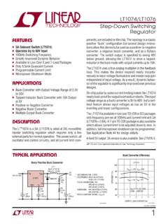
6 This principleis whatcausesthe arcingacrossthe contactsusedin switchesthat are in circuitswith switchjust beginsto open,the high voltagegeneratedallowselectronsto jumpthe air gap so that the currentflow doesnot actuallystop capacitoracrossthe contactshelpsto reducethis the automobileignition,a capacitoris placedacrossthe pointsto minimizedamagedue to arcingwhenthe pointsbreakthe currentflowingin the low-voltagecoil winding(in car manuals,this capacitorisreferredto as acondenser). (PWM)All of the switchingconvertersthat will be coveredin this paperuse a formof outputvoltageregulationknownas PulseWidthModulation(PWM).Put simply,the feedbackloop adjusts(corrects)the outputvoltageby changingthe ON time of the switchingelementin the an exampleof how PWMworks,we will examinethe resultof applyinga seriesof squarewavepulsesto an L-C filter (seeFigure4).
7 Figure4. BasicPrinciplesof PWMThe seriesof squarewavepulsesis filteredand providesa DC outputvoltagethat is equalto the peakpulseamplitudemultipliedtimesthe duty cycle(dutycycleis definedas the switchON time dividedby thetotal period).This relationshipexplainshow the outputvoltagecan be directlycontrolledby changingtheON time of the mostcommonlyusedDC-DCconvertercircuitswi ll now be presentedalongwith the basicprinciplesof mostcommonlyusedswitchingconverteris the Buck, whichis usedto down-converta DC voltagetoa lowerDC voltageof the is essentialin systemsthat use distributedpowerrails (like24 V to 48 V), whichmustbe locallyconvertedto 15 V, 12 V or 5 V with very little Buckconverterusesa transistoras a switchthat alternatelyconnectsand disconnectsthe inputvoltageto an inductor(seeFigure5).
8 TONTOFFTOFFTONINDUCTORCURRENTEQUIVALENT DCLOAD CURRENTVINVOUTPWMCONTROLSWITCHLOADLDC++ September2012 RevisedSeptember2016 SubmitDocumentationFeedbackCopyright 2012 2016,TexasInstrumentsIncorporatedSwitchi ngRegulatorFundamentalsFigure5. BuckRegulatorThe lowerdiagramsshowthe currentflow paths(shownas the heavylines)whenthe switchis on and switchturnson, the inputvoltageis connectedto the differencebetweenthe inputand outputvoltagesis thenforcedacrossthe inductor,causingcurrentthroughthe inductorto ON time,the inductorcurrentflowsinto boththe load and the outputcapacitor(the capacitorchargesduringthis time).Whenthe switchis turnedoff, the inputvoltageappliedto the inductoris ,becausethecurrentin an inductorcan not changeinstantly,the voltageacrossthe inductorwill adjustto hold inputend of the inductoris forcednegativein voltageby the decreasingcurrent,eventuallyreachingthe pointwherethe diodeis turnedon.
9 The inductorcurrentthenflowsthroughthe load and backthroughthe capacitordischargesinto the load duringthe OFFtime,contributingto the total currentbeingsuppliedto the load (the total load currentduringthe switchOFFtime is the sum of the inductorand capacitorcurrent).The shapeof the currentflowingin the inductoris similarto BuckRegulatorInductorCurrentAs explained,the currentthroughthe inductorrampsup whenthe switchis on, and rampsdownwhentheswitchis off. The DC load currentfromthe regulatedoutputis the averagevalueof the peak-to-peakdifferencein the inductorcurrentwaveformis referredto as the inductorripplecurrent,and the inductoris typicallyselectedlargeenoughto keepthis ripplecurrentless than20%to 30%of theratedDC ++ September2012 RevisedSeptember2016 SubmitDocumentationFeedbackCopyright 2012 2016, DiscontinuousOperationIn mostBuckregulatorapplications,the inductorcurrentneverdropsto zeroduringfull-loadoperation(this is definedas continuousmodeoperation).
10 Overallperformanceis usuallybetterusingcontinuousmode,and it allowsmaximumoutputpowerto be obtainedfroma giveninputvoltageand applicationswherethe maximumload currentis fairlylow, it can be advantageousto thesecases,operatingin discontinuousmodecan resultin a smalleroverallconvertersize (becausea smallerinductorcan be used).Discontinuousmodeoperationat lowerload currentvaluesis generallyharmless,and evenconvertersdesignedfor continuousmodeoperationat full load will becomediscontinuousas the load currentisdecreased(usuallycausingno problems). Boostregulatortakesa DC inputvoltageand producesa DC outputvoltagethat is higherin valuethanthe input(but of the samepolarity).The Boostregulatoris shownin Figure7, alongwith detailsshowingthe pathof currentflow duringthe switchON and BoostRegulatorWheneverthe switchis on, the inputvoltageis forcedacrossthe inductorwhichcausesthe currentthroughit to increase(rampup).