Transcription of LTC1624 - High Efficiency SO-8 N-Channel Switching ...
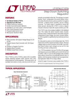
1 1 LTC1624 FEATURESDESCRIPTIONUnN-Channel MOSFET DrivenImplements Boost, Step-Down, SEPICand Inverting RegulatorsnWide VIN Range: to 36V OperationnWide VOUT Range: to 30V in Step-DownConfigurationn 1% ReferencenLow Dropout Operation: 95% Duty Cyclen200kHz Fixed FrequencynLow Standby CurrentnVery High EfficiencynRemote Output Voltage SensenLogic-Controlled Micropower ShutdownnInternal Diode for Bootstrapped Gate DrivenCurrent Mode Operation for Excellent Line andLoad Transient ResponsenAvailable in an 8-Lead SO PackagenNotebook and Palmtop Computers, PDAsnCellular Telephones and Wireless ModemsnBattery-Operated Digital DevicesnDC Power Distribution SystemsnBattery ChargersTYPICAL APPLICATIONUThe LTC 1624 is a current mode Switching regulatorcontroller that drives an external N-Channel power MOSFET using a fixed frequency architecture.
2 It can be operated inall standard Switching configurations including boost,step-down, inverting and SEPIC. Burst ModeTM operationprovides high Efficiency at low load currents. A maximumhigh duty cycle limit of 95% provides low dropout operationwhich extends operating time in battery-operated operating frequency is internally set to 200kHz, allowingsmall inductor values and minimizing PC board space. Theoperating current level is user-programmable via an externalcurrent sense resistor. Wide input supply range allowsoperation from to 36V (absolute maximum).A multifunction pin (ITH/ RUN) allows externalcompensation for optimum load step response plusshutdown. Soft start can also be implemented with theITH/ RUN pin to properly sequence 1.
3 High Efficiency Step-Down Converter++SENSE ITH/RUN VFB GND VIN BOOST TG SWLTC16241000pF100pFCC 470pFRC MBRS340T3CB FR2 20kCOUT 100 F 10V 2M1 Si4412 DYL1 10 H RSENSE CIN 22 F 35V 2 VOUT 2 AVIN TO 28V1624 F01, LTC and LT are registered trademarks of Linear Technology Mode is a trademark of Linear Technology Efficiency SO-8N-Channel SwitchingRegulator ControllerAPPLICATIONSU2 LTC1624 ABSOLUTE MAXIMUM RATINGSWWWUI nput Supply Voltage (VIN) .. 36V to Driver Supply Voltage (BOOST) .. 42V to Voltage (SW).. 36V to Boost Voltage(BOOST to SW) .. to VoltageVIN < 15V .. (VIN + ) to 15V .. (VIN + ) to (VIN 15V)ITH/RUN, VFB Voltages .. to Driver Output Current < 10 s (TG) .. 2 AOperating Temperature Range LTC1624CS.
4 0 C to 70 C LTC1624IS .. 40 C to 85 CJunction Temperature (Note 1) .. 125 CStorage Temperature Range .. 65 C to 150 CLead Temperature (Soldering, 10 sec) .. 300 CPACKAGE/ORDER INFORMATIONWUUORDER PARTNUMBERS8 PART MARKINGTOP VIEWVIN BOOST TG SWSENSE ITH/RUN VFB GNDS8 PACKAGE 8-LEAD PLASTIC SO1 2 3 48 7 6 5 TJMAX = 125 C, JA = 110 C/ WLTC1624CS8 LTC1624IS816241624 IConsult factory for Military grade CHARACTERISTICSTA = 25 C, VIN = 15V, unless otherwise Control LoopIIN VFBF eedback Current(Note 2)1050nAVFBF eedback Voltage(Note 2) VLINE REGR eference Voltage Line RegulationVIN = to 20V (Note 2) V VLOAD REGO utput Voltage Load Regulation(Note 2)ITH Sinking 5 Al Sourcing 5 Al Overvoltage DC Supply Current(Note 3)
5 Normal Mode550900 AShutdownVITH/RUN = 0V1630 AVITH/RUNRun Current SourceVITH/RUN = ARun Pullup CurrentVITH/RUN = 1V 50 160 350 A VSENSE(MAX)Maximum Current Sense ThresholdVFB = Transition TimeTG tr Rise TimeCLOAD = 3000pF50150nsTG tf Fall TimeCLOAD = 3000pF50150nsfOSCO scillator Frequencyl175200225kHzVBOOSTB oost VoltageSW = 0V, IBOOST = 5mA, VIN = VBOOSTB oost Load RegulationSW = 0V, IBOOST = 2mA to 20mA35%TJ = TA + (PD 110 C/W)Note 2: The LTC1624 is tested in a feedback loop which servos VFB tothe midpoint for the error amplifier (VITH = ).Note 3: Dynamic supply current is higher due to the gate charge beingdelivered at the Switching frequency. See Applications l denotes specifications which apply over the full operatingtemperature : 0 C TA 70 CLTC1624IS: 40 C TA 85 CNote 1: TJ is calculated from the ambient temperature TA and powerdissipation PD according to the following formula.
6 3 LTC1624 TYPICAL PERFORMANCE CHARACTERISTICS UWEfficiency vs Load CurrentVOUT = CURRENT (A) Efficiency (%)100 95 90 85 80 75 = 5V VIN = 10V RSENSE = LOAD CURRENT (A) Efficiency (%)100 95 90 85 80 75 = RSENSE = VIN = 5 VVIN = 10 VEfficiency vs Input VoltageVOUT = VOLTAGE (V)0 Efficiency (%)100 95 90 85 80 75 70 15251624 G095102030 ILOAD = 1 AVOUT = RSENSE = ILOAD = vs Load CurrentVOUT = 5 VEfficiency vs Input VoltageVOUT = 5 VInput Supply Current vsInput VoltageBoost Line RegulationINPUT VOLTAGE (V)0 BOOST VOLTAGE (V)6 5 4 3 2 1 015251624 G04510203035 IBOOST = 1mA VSW = 0 VBOOST LOAD CURRENT (mA)0 BOOST VOLTAGE (V)6 5 4 3 2 1 015251624 G065102030 VSW = 0 VVIN = 15 VVIN = 5 VBoost Load RegulationTEMPERATURE ( C) 40 BOOST VOLTAGE (V) G15 151060110135 ILOAD = 1mALOAD CURRENT (A)VIN VOUT (V) 0 1624 = VOUT DROP OF 5%INPUT VOLTAGE (V)0 SUPPLY CURRENT ( A)700 600 500 400 300 200 100 015251624 G05510203035 SLEEP MODEVFB = VOLTAGE (V)0 Efficiency (%)100 95 90 85 80 75 70 15251624 G105102030 ILOAD = 1 AVOUT = 5V RSENSE = ILOAD = VOUT Dropout Voltagevs Load CurrentBoost Voltage vs Temperature4 LTC1624 TYPICAL PERFORMANCE CHARACTERISTICS UWVITH/RUN (V) (MAX)IOUT(a)1624 G01 IOUT(MAX)SHUTDOWNACTIVE MODEVITH vs Output CurrentTEMPERATURE ( C) 40 ITH/RUN PIN SOURCE CURRENT WITH VITH = 1V ( A)
7 ITH/RUN PIN SOURCE CURRENT WITH VITH = 0V ( A)300 250 200 150 100 50 05 4 3 2 1 035851624 G14 151060110135 ITH/RUN = 1 VITH/RUN = 0 VITH/RUN Pin Source Current vsTemperatureIITH vs VITHIITH ( A)2001505003 VITH (V) (b)1624 G02 SHUTDOWNACTIVE MODE Frequency vs Feedback VoltageFEEDBACK VOLTAGE0 FREQUENCY (kHz)250 200 150 100 50 ( C) 40 CURRENT SENSE THRESHOLD (mV)170 168 166 164 162 160 158 156 154 152 1501060851448 G13 1535110135 Maximum Current SenseThreshold vs TemperatureTEMPERATURE ( C) 40 FREQUENCY (kHz)250 200 150 100 50 01060851448 G12 1535110135 VOUT IN REGULATIONVFB = 0 VPIN FUNCTIONSUUUSENSE (Pin 1): Connects to the ( ) input for the currentcomparator. Built-in offsets between the SENSE and VINpins in conjunction with RSENSE set the current trip thresh-olds.
8 Do not pull this pin more than 15V below VIN or morethan below (Pin 2): Combination of Error Amplifier Compen-sation Point and Run Control Inputs. The current com-parator threshold increases with this control voltage range for this pin is to Forcingthis pin below causes the device to be shut down. Inshutdown all functions are disabled and TG pin is held (Pin 3): Receives the feedback voltage from an exter-nal resistive divider across the (Pin 4): Ground. Connect to the ( ) terminal of COUT,the Schottky diode and the ( ) terminal of (Pin 5): Switch Node Connection to Inductor. In step-down applications the voltage swing at this pin is from aSchottky diode (external) voltage drop below ground Frequency vsTemperature5 LTC1624TG (Pin 6): High Current Gate Drive for Top N-ChannelMOSFET.
9 This is the output of a floating driver with avoltage swing equal to INTVCC superimposed on theswitch node voltage (Pin 7): Supply to Topside Floating Driver. Thebootstrap capacitor CB is returned to this pin. Voltageswing at this pin is from INTVCC to VIN + INTVCC in step-down applications. In non step-down topologies the volt-age at this pin is constant and equal to INTVCC if SW = (Pin 8): Main Supply Pin and the (+) Input to theCurrent Comparator. Must be closely decoupled to FUNCTIONSUUU(Refer to Functional Diagram)OPERATIOUMain Control LoopThe LTC1624 uses a constant frequency, current modearchitecture. During normal operation, the top MOSFET isturned on each cycle when the oscillator sets the RS latchand turned off when the main current comparator I1 resetsthe RS latch.
10 The peak inductor current at which I1 resetsthe RS latch is controlled by the voltage on the ITH/ RUNpin, which is the output of error amplifier EA. The VFB pin,described in the pin functions, allows EA to receive anoutput feedback voltage from an external resistive the load current increases, it causes a slightdecrease in VFB relative to the reference, which inturn causes the ITH/ RUN voltage to increase until theaverage inductor current matches the new load the top MOSFET is off, the internal bottom MOSFETis turned on for approximately 300ns to 400ns to rechargethe bootstrap capacitor top MOSFET driver is biased from the floating boot-strap capacitor CB that is recharged during each off dropout detector counts the number of oscillatorcycles that the top MOSFET remains on and periodicallyforces a brief off period to allow CB to main control loop is shut down by pulling the ITH/ RUNpin below its clamp voltage.