Transcription of SWITCHMODE Series NPN Silicon Power …
1 Semiconductor Components Industries, LLC, 2011 October, 2011 Rev. 101 Publication Order Number:MJE13009/DMJE13009 GSWITCHMODE SeriesNPN Silicon PowerTransistorsThe MJE13009G is designed for high voltage, high speed powerswitching inductive circuits where fall time is critical. They areparticularly suited for 115 and 220 V SWITCHMODE applicationssuch as Switching Regulators, Inverters, Motor Controls,Solenoid/Relay drivers and Deflection VCEO(sus) 400 V and 300 V Reverse Bias SOA with Inductive Loads @ TC = 100_C Inductive Switching Matrix 3 to 12 Amp, 25 and 100_C tc @ 8 A,100_C is 120 ns (Typ)
2 700 V Blocking Capability SOA and Switching Applications Information These Devices are Pb Free and are RoHS Compliant*MAXIMUM RATINGSR atingSymbolValueUnitCollector Emitter VoltageVCEO(sus)400 VdcCollector Emitter VoltageVCEV700 VdcEmitter Base VoltageVEBO9 VdcCollector Current Continuous Peak (Note 1)ICICM1224 AdcBase Current Continuous Peak (Note 1)IBIBM612 AdcEmitter Current Continuous Peak (Note 1)IEIEM1836 AdcTotal Device Dissipation @ TA = 25_CDerate above 25 Device Dissipation @ TC = 25_CDerate above 25 and Storage JunctionTemperature RangeTJ, Tstg 65 to+150_CTHERMAL CHARACTERISTICSC haracteristicsSymbolMaxUnitThermal Resistance, Junction to Resistance, Junction to Lead Temperature for SolderingPurposes 1/8 from Case for 5 SecondsTL275_CStresses exceeding Maximum Ratings may damage the device.
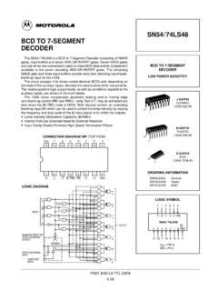
3 MaximumRatings are stress ratings only. Functional operation above the RecommendedOperating Conditions is not implied. Extended exposure to stresses above theRecommended Operating Conditions may affect device Pulse Test: Pulse Width = 5 ms, Duty Cycle 10%.*For additional information on our Pb Free strategy and soldering details, pleasedownload the ON Semiconductor Soldering and Mounting TechniquesReference Manual, AMPERENPN SILICONPOWER TRANSISTOR400 VOLTS 100 WATTSTO 220 ABCASE 221A 09 STYLE 11 DIAGRAM23 MJE13009 GAY WWA= Assembly LocationY= YearWW= Work WeekG= Pb Free PackageDevicePackageShippingORDERING INFORMATIONMJE13009 GTO 220(Pb Free)
4 50 Units / RailMJE13009 ELECTRICAL CHARACTERISTICS (TC = 25_C unless otherwise noted) Characteristic Symbol Min Typ Max Unit OFF CHARACTERISTICS (Note 2) Collector Emitter Sustaining Voltage(IC = 10 mA, IB = 0) VCEO(sus) 400 Vdc Collector Cutoff Current(VCEV = Rated Value, VBE(off) = Vdc)(VCEV = Rated Value, VBE(off) = Vdc, TC = 100_C) ICEV 15 mAdc Emitter Cutoff Current(VEB = 9 Vdc, IC = 0)
5 IEBO 1 mAdc SECOND BREAKDOWN Second Breakdown Collector Current with base forward biasedClamped Inductive SOA with Base Reverse Biased IS/b See Figure 1 See Figure 2 ON CHARACTERISTICS (Note 2) DC Current Gain(IC = 5 Adc, VCE = 5 Vdc)(IC = 8 Adc, VCE = 5 Vdc) hFE 86 4030 Collector Emitter Saturation Voltage(IC = 5 Adc, IB = 1 Adc)(IC = 8 Adc, IB = Adc)(IC = 12 Adc, IB = 3 Adc)(IC = 8 Adc, IB = Adc, TC = 100_C) VCE(sat)
6 Vdc Base Emitter Saturation Voltage(IC = 5 Adc, IB = 1 Adc)(IC = 8 Adc, IB = Adc)(IC = 8 Adc, IB = Adc, TC = 100_C) VBE(sat) Vdc DYNAMIC CHARACTERISTICS Current Gain Bandwidth Product(IC = 500 mAdc, VCE = 10 Vdc, f = 1 MHz) fT 4 MHz Output Capacitance(VCB = 10 Vdc, IE = 0, f = MHz)
7 Cob 180 pF SWITCHING CHARACTERISTICS Resistive Load (Table 1) Delay Time (VCC = 125 Vdc, IC = 8 A,IB1 = IB2 = A, tp = 25 ms,Duty Cycle v 1%) td ms Rise Time tr 1 ms Storage Time ts 3 ms Fall Time tf ms Inductive Load, Clamped (Table 1, Figure 13) Voltage Storage Time (IC = 8 A, Vclamp = 300 Vdc,IB1 = A, VBE(off) = 5 Vdc, TC = 100_C)
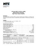
8 Tsv ms Crossover Time tc ms2. Pulse Test: Pulse Width = 300 ms, Duty Cycle = 2%.MJE13009 , COLLECTOR CURRENT (AMP)10 m 100 m 1 m sdc1007 VCE, COLLECTOR-EMITTER VOLTAGE (VOLTS) 100 Figure 1. Forward Bias Safe Operating AreaFigure 2. Reverse Bias Switching SafeOperating 100 CIB1 = A500700 VBE(off) = 9 V06 VCEV, COLLECTOR-EMITTER CLAMP VOLTAGE (VOLTS)102004006005 V215TC = 25 C12843 , COLLECTOR (AMP)200 THERMAL LIMITBONDING WIRE LIMITSECOND BREAKDOWN LIM ITCURVES APPLY BELOW RATEDVCEOThe Safe Operating Area figures shown in Figures 1 and 2 are specified ratings for these devices under the test conditions 3.
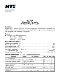
9 Forward Bias Power DeratingTC, CASE TEMPERATURE ( C) DERATING FACTORSECOND BREAK DOWN are two limitations on the Power handling ability ofa transistor: average junction temperature and secondbreakdown. Safe operating area curves indicate IC VCElimits of the transistor that must be observed for reliableoperation; , the transistor must not be subjected to greaterdissipation than the curves data of Figure 1 is based on TC = 25_C; TJ(pk) isvariable depending on Power level.
10 Second breakdownpulse limits are valid for duty cycles to 10% but must bederated when TC 25_C. Second breakdown limitations donot derate the same as thermal limitations. Allowablecurrent at the voltages shown on Figure 1 may be found atany case temperature by using the appropriate curve onFigure (pk) may be calculated from the data in Figure 4. At highcase temperatures, thermal limitations will reduce the powerthat can be handled to values less than the limitationsimposed by second breakdown.