Transcription of Synchronizing Controller Area Network and Analog Input ...
1 1. NATIONA L INSTRU MEN TS. A PPLIC ATI O N N OTES. Synchronizing Controller area Network and Analog Input Measurements for In-Vehicle Data Logging Abstract This application note discusses the technique and importance of Synchronizing data acquisition signals from sensors and data from the Controller area Network (CAN) for in-vehicle applications. This technique has several challenges including the multitude of different signals and sensors available, synchronization techniques, and the post-processing and analysis of the synchronized data. This application note covers recommended best practices for Synchronizing data acquisition signals and vehicle Network communications. David Ashlock Applications Engineer, national instruments Introduction to Synchronization for In-Vehicle Data 2. Different Types of Input Signals for 3. Controller area Network 3. Analog 4. Digital 4. Global Positioning 4. Multiple Synchronization Techniques for In-Vehicle Data 4. Software 4.
2 Hardware 5. Challenges of Synchronizing Sample Rates .. 5. Post-Processing and Analysis of Synchronized 6. Additional 6. 7. Introduction to Synchronization for In-Vehicle Data Logging In-vehicle data logging occurs in the later stages of automotive testing. It is often used to test and verify the operation of an automotive feature, such as an electric power-assist steering system. An automotive feature is a complex operation that may require Input from multiple electronic control units (ECUs), which communicate through an in-vehicle Network like CAN to operate properly. A typical top-of-the-range vehicle comprises over 30 electronic systems (for example, airbags, doors, and transmission) and more than 100 sensors (pressure, temperature, parking, and so on)1. For example, a company trying to ensure a smooth driving experience might need to validate active suspension and characterize how the automobile is reacting to the road. This test requires a data acquisition (DAQ) system to acquire and log data from automotive sensors that measure vibration as well as monitor more than one ECU that is a part of this system.
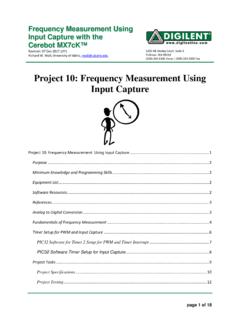
3 There are a wide range of applications for in-vehicle data logging and each requires many considerations to validate a feature, electronic control unit, or an automotive sensor. Current Position ECU. Torque Sensor Motor Assist Torque Figure 1. This is a diagram of an electric power-assist steering system, a feature in automobiles that acquires Analog Input measurements in order to determine the appropriate amount of motor voltage to be applied. As the electronic complexity of vehicles has increased so too has the importance of automotive sensors and Network communication. This has placed an added importance on the incorporation of in-vehicle networks like CAN in the testing phase. The ability to synchronize CAN transmissions with these other elements is an important characteristic of a data acquisition system to achieve repeatable measurement results. To validate these systems, you need to understand everything that happens at each instance, which makes synchronization necessary.
4 For example, to validate hydraulic actuated active suspension, the data received from the vibration sensors needs to correspond to the appropriate CAN. message to ensure the hydraulic servos are applying the correct counter forces. With synchronization of these signals and messages, an engineer can validate hydraulic actuated active suspension with confidence, because the data from a number of different sources is now correlated appropriately. There are several considerations when Synchronizing data acquisition signals and CAN transmissions. These can include the different types of Input signals and sensors for automotive applications, the differences between hardware and software synchronization, and the post-processing and analysis of synchronized data. In this application note, review the best techniques to perform synchronization of data acquisition signals and CAN transmissions for in-vehicle data logging. The end goal is an accurate representation of a feature, an ECU, and an automotive sensor's performance.
5 [ back to page one ] | 2. This application note uses NI cDAQ-9174, NI 9201, and NI 9862 C Series hardware for the synchronization and data acquisition. Different Types of Input Signals for Synchronization In a modern-day automobile, multiple types of signals are often involved. Depending on the in-vehicle data-logging application, different signals such as CAN, voltage, current, pressure, PWM, GPS, and so on may be required. To continue the previous example, for an active suspension system, there are Analog sensors that measure the vibration of the automobile and CAN transmissions relay commands to the hydraulic servos to ensure a smooth ride. In addition, digital signals alert users when active suspension is engaged and GPS data could be used to correlate locations with the amount of hydraulic servo action. To discuss the challenges associated with logging this data, you first need to have a deeper understanding for the different signals that an engineer would encounter for these applications.
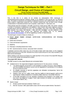
6 Controller area Network Protocol Some electronic control units form independent subsystems, but communications between other systems are essential. A subsystem may need to control actuators or receive feedback from sensors and distribute this information to another system. The CAN protocol was created to be a reliable communication method to transmit and receive data from different ECUs. While CAN connects ECUs, smart sensors and actuators can now also connect and communicate directly on the bus like an ECU would. A CAN message contains an identifier, a native timestamp, and up to 8 bytes of data. A CAN message can either be transmitted at a regular interval or be event driven. This is an important difference between a CAN message and Analog signals, which are sampled at a regular interval. Figure 2 demonstrates an electric power-assist steering system in which the CAN message is sent to control the motor based on the torque signal and vehicle speed received.
7 Motor Voltage CAN Bus ECU. Synchronized Motor Sampling Steering Torque signal 0. 1. Analog 2. 3. 4. Input 6. 7. 8. 9. Vehicle Speed signal Figure 2. The system samples the steering torque and vehicle speed that are being delivered to the ECU. A CAN message is sent to alter the motor voltage based on the steering torque and vehicle speed received. The engineer can log CAN and DAQ messages simultaneously to determine if the desired motor output is being produced. [ back to page one ] | 3. Analog signal For in-vehicle data-logging applications, you can't validate a feature with only CAN communication. You need to gather data from different sources, such as Analog sensors. Depending on what type of Analog signal you are measuring, you can use a wide range of sensors (O2, ECT, MAF, vehicle speed, crankshaft position, and so on). Each sensor requires a different sampling rate. For example, it is not necessary to sample the vehicle speed sensor at 100 kHz because the speed for an automobile typically won't alter dramatically in a second.
8 However, with a crankshaft position sensor, it may be necessary to sample at 100 kHz because of the possible instantaneous change and importance of this sensor data. You need to find the right automotive sensors based on the environmental and signal considerations and sampling rate. In Figure 2, the Analog sensors measure torque and vehicle speed and when these sensors reach a specified threshold, a CAN message is sent to alter the motor voltage. Digital signal Digital signals can also be vital to certain systems. For in-vehicle data-logging applications, the typical digital signal will be measured or distributed as a high or low, PWM, or counter signal . In an automobile, the user wants to know when certain systems are operational, whether these systems are of high importance or not. For example, when you change the airflow, an LED is illuminated to show what setting the air conditioner is on. Another example of high importance is in an electric vehicle where a PWM signal is used to control motor output, which is critical to the operation of the vehicle.
9 Global Positioning System Another common type of data in vehicles is global positioning system (GPS). GPS is a radio frequency encoded signal that provides time, position, and velocity information by means of a Network of triangulation satellites2. A vehicle uses GPS for many different reasons, such as tracking, Network management, and monitoring user information. GPS information is vitally important for fleet recording to ensure that the location of testing is recorded when it comes to the post-processing and analysis stage of testing. For an ambulance Network management, when someone has to be rushed to the hospital, the response time is vitally important. One interesting solution is to use a GPS-based fleet control system. The main targets are to know the exact location and the state (on duty or off duty) of all its ambulances at all times and to plan the ideal route to arrive at the suitable medical center from the help call place3. Multiple Synchronization Techniques for In-Vehicle Data Logging You can synchronize CAN and sensor signals for in-vehicle data logging through two ways: software or hardware.
10 To ensure the most accurate synchronization, you must take into account clock drift and start and stop latency by using hardware synchronization over software synchronization with the available Real-Time System Integration (RTSI) bus or onboard clocks. If the data is synchronized via hardware, the Analog channel data will correspond with the appropriate CAN. message because there is no concern of clock drift or latency. Software Synchronization You can design an application to use software synchronization for sensor signals and CAN because both signals contain a timestamp. However, using software synchronization, there is no guarantee on the accuracy of the timestamps themselves because of clock drift and start and stop latency4. Clock Drift Clock oscillators are built with inherent frequency instability or jitter, therefore over time any two unsynchronized clocks drift relative to each other. For many validation applications, this amount of clock drift is unacceptable, especially in the cases of fleet recording due to the extended time of testing.