Transcription of TAS2770 Digital Input Mono Class-D Audio Smart Amplifier ...
1 TAS2770 20-W Digital Input Mono Class-D Audio Amplifier with Speaker I/V Sense1 Features High-Performance Mono Class-D Amplifier 20-W at 1% THD+N (4 , 16 V) at 1 % THD+N (4 , V) % THD+N at 1 W (4 , VBAT = V) 32- Vrms A-Weighted Idle Channel noise 90-dB PSRR with 200 mVPP Ripple at 20 - 20 kHz Efficiency at 1 W (4 , VBAT = V) < 1 A HW Shutdown VBAT Current 42 mW / 63 mW Idle Dissipation ( V / V) Speaker Voltage and Current Sense Real-Time Diagnostics Using I/V Speaker Sense Over Current Short Circuit(short to power, short to groundand terminal-to-terminal short) Over-Temperature VBAT Tracking Peak Voltage Limiter with BrownOut Prevention to 192-kHz Sample Rates Flexible User Interfaces I2S/TDM: 8 Channels (32-bit / 96 kHz) I2C: 8 selectable Addresses MCLK Free Operation Low Pop and Click Power Supplies VBAT: V to 16 V AVDD: V Spread-Spectrum Low EMI Mode Thermal and Over Current Protection2 Applications Laptop Computers Bluetooth Speakers Home Automation Smart Speakers/IoT3 DescriptionThe TAS2770 is a mono, Digital Input Class-D audioamplifier optimized for efficiently driving smallloudspeakers.
2 The output power, protection featuresand packages make TAS2770 a good choice forSmart speakers, Bluetooth speakers, homeautomation devices, Notebook computers and Class-D Amplifier is capable of delivering 20W ofcontinuous power into a 4- load at 16V and 15W intoan 8- load at 16V both at 1% THD. The broadvoltage Input range of and the high outputpower makes this Amplifier versatile enough to workwith battery power or with line powered systemsA Brown-Out preventer tracks peak voltage andautomatically self-limits the gain to the voltageavailable. This hardware implemented featurereduces the Amplifier s demand on system powerpreventing both Audio cut out and system shutdownThe TAS2770 can be used as a conventional amp orwith host based speaker protection algorithms.
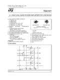
3 Theintegrated speaker voltage and current senseprovides for real time feedback of loudspeakerconditions to the protection algorithms through areturn I2S to eight devices can share a common bus viaeither I2S/TDM + TAS2770 device is available in a 26-pin, QFN for a compact PCB InformationPART NUMBERPACKAGEBODY SIZE (NOM) TAS2770 QFN4 mm mmTAS2770 DSBGA2 mm mmSNP002770 QFN4 mm mmSNP002770 DSBGA2 mm mmSDOUTFSYNCSBCLKOUT_POUT_NClass-D AmplifierwithIV-SenseVREGGNDAREGSDZPGNDD ACS ystemInterface+ VVBATSARADCTMP SNSPop/ClickOver CurrentOver VCopyright 2016, Texas Instruments IncorporatedFunctional Block OCTOBER 2017 REVISED OCTOBER 2020 Copyright 2020 Texas Instruments IncorporatedSubmit Document Feedback1 Product Folder Links.
4 TAS2770 TAS2770 SLASEM6C OCTOBER 2017 REVISED OCTOBER 2020An IMPORTANT NOTICE at the end of this data sheet addresses availability, warranty, changes, use in safety-critical applications,intellectual property matters and other important disclaimers. PRODUCTION of Contents1 Revision Pin Configuration and Absolute Maximum ESD Recommended Operating Thermal Electrical I2C Timing TDM Port Timing PDM Port Timing Typical Parameter Measurement Detailed Functional Block Feature Device Functional Register Application and Application Typical Initialization Set Power Supply Layout Layout Device and Documentation Receiving Notification of Documentation Community Mechanical, Packaging, and Revision HistoryNOTE.
5 Page numbers for previous revisions may differ from page numbers in the current from Revision B (October 2018) to Revision C (October 2020)Page Changed information on front page ..1 Changed VBAT Max in Section from 16 V to 18 Changed from Revision A (December 2017) to Revision B (October 2018)Page Changed From: Efficiency (%) To: VDD PSRR (dB) in Figure 6-15 ..13 Changed From: Efficiency (%) To: VBAT PSRR (dB) in Figure 6-16 ..13 Changes from Revision * (October 2017) to Revision A (December 2017)Page Released TAS2770 as Production Data ..1 TAS2770 SLASEM6C OCTOBER 2017 REVISED OCTOBER Document FeedbackCopyright 2020 Texas Instruments IncorporatedProduct Folder Links: TAS27705 Pin Configuration and Functions20 IRQZ21 SDZ22 SDA23 SCL24 AREG25 VBAT26 OUT_NSBCLK13 SDOUT12 SDIN11 GND10 AVDD9 IOVDD8 DREG7 VSNS_N61 BST_N2 PGND3 OUT_P4 BST_P5 VSNS_P14 FSYNC15 GND16 GND17 PDMCK18 PDMD19 MODEP reliminaryDrawing is 5-1.
6 QFN Package 26-Pin RJQ Top View1 2 3 4 5 A B C D E F Not to scaleVSNS_PBST_NOUT_PPGNDOUT_NVSNS_NBST_ POUT_PPGNDOUT_NAVDDGNDSDZVBATVBATDREGIOV DDMODEIRQZAREGSDOUTFSYNCGNDGNDPDMDSBCLKS DINSDASCLPDMCKF igure 5-2. WCSP 30-Ball Top OCTOBER 2017 REVISED OCTOBER 2020 Copyright 2020 Texas Instruments IncorporatedSubmit Document Feedback3 Product Folder Links: TAS2770 Pin FunctionsPINI/ODESCRIPTIONDSBGAQFNNAMED5 24 AREGOGate drive voltage regulator output. Decouple with cap to GND. Do not connectto external power Input . Connect to supply and decouple to GND with negative bootstrap. Connect a cap between BST_N and positive bootstrap.
7 Connect a cap between BST_P and core voltage regulator output. Bypass to GND with a cap. Do notconnect to external Frame , E3,E410, 15,16 GNDPA nalog GND. Connect to PCB GND IO Supply. Connect to the same V supply that powers AVDD anddecouple with a cap to drain, actve low interrupt pin. Pull up to IOVDD with resistor if optionalinternal pull up is not detect pin. This pin can detect a short to IOVDD or GND, a 470 connection to IOVDD or GND, a k connection to IOVDD or GND, a 10 k connection to IOVDD or GND and a 47 k connection to IOVDD. Minimizecapacitive loading on this pin and do not connect to any other , B526 OUT_NOClass-D negative , B33 OUT_POClass-D positive Digital , B42 PGNDPC lass-D GND.
8 Connect to PCB GND Serial Bit Clock in TDM/I2C Clock Pin. Pull up to IOVDD with a Data Pin. Pull up to IOVDD with a Serial Data Serial Data Output in TDM/I2C low hardware , C525 VBATPC lass-D power supply Input . Connect to VBAT supply and decouple with a Sense negative Input . Connect to Class-D negative output after Ferritebead Sense positive Input . Connect to Class-D positive output after Ferritebead OCTOBER 2017 REVISED OCTOBER Document FeedbackCopyright 2020 Texas Instruments IncorporatedProduct Folder Links: TAS27706 Absolute Maximum Ratingsover operating free-air temperature range (unless otherwise noted) (1)MINMAXUNITS upply VoltageAVDD voltage(2) Digital IOs referenced to IOVDD supply free-air temperature, TA ; Device is functional and reliable, some performancecharacteristics may be degraded.
9 4085 CPerformance free-air temperature, TP ; All performance characteristics are met. 2070 COperating junction temperature, TJ 40150 CStorage temperature, Tstg 65150 C(1) Stresses beyond those listed under Absolute Maximum Ratings can cause permanent damage to the device. These are stress ratingsonly, which do not imply functional operation of the device at these or any other conditions beyond those indicated underRecommended Operating Procedures. Exposure to absolute-maximum-rated conditions for extended periods can affect devicereliability.(2) All Digital inputs and IOs are ESD RatingsVALUEUNITV(ESD)Electrostatic dischargeHuman-body model (HBM), per ANSI/ESDA/JEDEC JS-001(1) 2500 VCharged-device model (CDM), per JEDEC specification JESD22-C101(2) 1500(1) JEDEC document JEP155 states that 500-V HBM allows safe manufacturing with a standard ESD control process.
10 (2) JEDEC document JEP157 states that 250-V CDM allows safe manufacturing with a standard ESD control Recommended Operating Conditionsover operating free-air temperature range (unless otherwise noted)MINNOMMAXUNITAVDDS upply Digital Input voltageIOVDDVVILLow-level Digital Input voltage0 VRSPKM inimum speaker LSPKM inimum speaker inductance10 Thermal InformationTHERMAL METRIC(1) TAS2770 UNITQFN (RJQ)26 PINSR JAJunction-to-ambient thermal C/WR JC(top)Junction-to-case (top) thermal C/WR JBJunction-to-board thermal C/W JTJunction-to-top characterization C/W JBJunction-to-board characterization OCTOBER 2017 REVISED OCTOBER 2020 Copyright 2020 Texas Instruments IncorporatedSubmit Document Feedback5 Product Folder Links.