Transcription of Techniques for Robust Touch Sensing Design
1 2010-2013 Microchip Technology 1AN1334 INTRODUCTIONThe purpose of this application note is to describe thebest Design practices when developing capacitivetouch applications for noisy environments. Thisapplication note will begin by defining the problemscaused by noise , and explain how that noise typicallyaffects systems. Hardware guidelines will then beprovided to help maximize the natural signal-to-noiseratio (SNR) of the application. Software Techniques arethen covered to describe some of the commonmethods used to filter a sensor s signal to increase theSNR further, and then to make a decoding decisionbased on the behavior of the capacitive hardware Design topics that will be covered and slider pad Design and material and layer trace layout and series Techniques for ESD supply grounding VDD and bypass capacitorsmTouch and RightTouch Sensing solution systemshave passed industry test standards in conducted andradiated susceptibility, and radiated emissions.
2 Thisapplication note describes the important aspects ofcapacitive Touch Design which, when coupled with goodprinted circuit board (PCB) Techniques , will allow thesesystems to continue performing in these extremetesting information on the basics of capacitive touchsensing and other more advanced topics, visit theMicrochip Touch and input Sensing solutions web site Capacitive Touch ReviewCapacitive sensors are areas on a PCB that have beenfilled with copper and then connected back to the PIC device using a trace. The PIC device will then measurethe sensor in some manner that allows it to notice smallshifts in capacitance typically caused by a user s fingerapproaching the sensor. The capacitance iscontinuously read in software and when a changeoccurs, the system will register a press on that sensor.
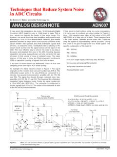
3 In Figure 1, CBASE is the capacitance value when noobject is over the pad. This is referred to as thesensor s base capacitance. CF is the capacitancechange caused by a finger Touch , and CT is the totalcapacitance of the 1:CAPACITIVE SENSOR SYSTEMThe capacitances in this system can be calculated bythe parallel plate capacitance shown in Equation 2. It isimportant to understand that in real applications thecapacitive sensor system is much more complex thanEquation 1. Generally speaking, the system could beconsidered as a network of capacitors, resistors, andinductors which are a result of the PCB, the overlay, thehuman body, and the environment. Therefore, it is verydifficult to calculate the exact characteristics of acapacitive sensor recommendations in this application note arebased on lab test results and are not absoluteconditions.
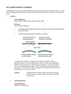
4 Users can always make their ownadjustments based on the capacitance equation andtheir own application s :Burke DavisonMicrochip Technology = C0 + CFTechniques for Robust Touch Sensing DesignAN1334DS00001334B-page 2 2010-2013 Microchip Technology 1:PARALLEL PLATE CAPACITANCET here are two fundamental methods for detecting ashift in capacitance using a microcontroller. The first isto use a voltage measurement where the systemmanipulates the pin of the sensor, to place a voltagebased on the amount of capacitance on the pin, andlooks for a shift in the voltage reading on the includes methods such as Microchip s ChargeTime Measurement Unit (CTMU) and CapacitiveVoltage Divider (CVD). The alternative is to measurethe sensor using a frequency approach, such as theRightTouch scanning method, which uses apseudo-randomized frequency to sense changes incapacitance.
5 The waveforms for all three scanningmethods can be found below in Figure 2:CAPACITIVE Sensing ACQUISITION WAVEFORMSA cquisition WaveformsThis application note will focus on the hardware designof the system and the sections of firmware not involvedin signal acquisition. For designs implementing theCVD or CTMU Techniques , the source code available inthe Microchip Library of Applications implements thisfor the designer. If using a RightTouch turnkey product,these Techniques are built-in as part of the solution. noise Immunity vs. Low PowerWhen developing a capacitive Touch system, it isimportant to know what your main goal should be fromthe very start of product development. For the majorityof applications, how the system is powered will answerthis question. For line-powered systems, conductednoise immunity is the main concern.
6 Forbattery-powered systems, low power is the mainconcern. It is also possible that some systems may overlapbetween these two regions. A cell phone that has theoption of being powered through a USB cable is oneexample. The majority of the time, it would beconcerned with low power; however, it needs to becareful of conducted noise when being poweredthrough the main line. For this reason, onlyvoltage-based acquisition methods should be used inthese systems. While noise immunity and low power are not mutuallyexclusive, focusing on one will require that designtrade-offs be made to the other. For example, imple-menting a slew rate limiter filter to reduce susceptibilityto conducted noise will require increasing the samplerate of the system, which will increase the overallpower consumption.
7 Lowering VDD is an excellent ideain low-power applications, but doing so will alsodecrease your noise immunity (see Section PowerSupply Considerations). This application note focuseson decreasing noise susceptibility and treats low poweras a secondary goal. If low power is the main goal ofthe application, visit formore technical OF noise ON CAPACITIVE Touch SENSORSPush Buttons vs. Capacitive SensorsBefore considering how to develop a Robust capacitivetouch application, it is important to understand thefundamental reason why noise is a concern. Whenusing a mechanical button, the microcontroller s portcircuitry decides whether the switch s pin is beingpulled high or low and provides a single-bit digital resultto the user. This result is then debounced to adjust forringing, and the state of the button is based on the stateof the debounce Touch sensor applications, however, areanalog.
8 The first clear difference is the need tomanually perform the reading process. When using amechanical switch, the microcontroller is able to readthe pin using its internal hardware logic. For capacitivetouch applications, separate hardware modules willneed to be used to manipulate the sensor line. Whetherit is using a voltage-based measurement or afrequency-based measurement, the analog result willbe provided in the form of an integer value. This valueis then typically filtered using different digital signalprocessing Techniques to amplify the signal andattenuate the noise . The filter value is then sentthrough some form of debounce algorithm and a morecomplex decoding process. An extra layer ofcomplexity is also added when the system is designedto perform in a closed loop manner, adjusting itsbehavior based on the sensor s current r 0Ad---=Where.
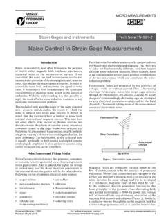
9 R = relative permittivity of the dielectric material 0 = permittivity of space ( x 10-12 F/m)A = plate area in square meters (m2)d = distance between the plates in meters (m)Charge Time Measurement Unit(CTMU)Capacitive Voltage Divider(CVD)RightTouch Sensing (CAPxxxx Devices) 2010-2013 Microchip Technology 3AN1334 The capacitive Touch software process can besimplified into three distinct a voltage-based or frequency-basedmeasurement technique to obtain a sample fromthe capacitive Touch the incoming sensor samples toincrease the effective SNR of the system byattenuating the whether a sensor is pressed orreleased based on the current value of the sen-sor samples and the sensor s previous 3 illustrates the difference between pushbuttons and capacitive Touch sensors, and labels thethree main software stages of a capacitive 3:PUSH BUTTON VS.
10 CAPACITIVE SENSOR SOFTWARE PROCESSC onducted and Radiated noise Conducted and radiated are the two mainclassifications of injected noise that can createinstability in capacitive Touch systems. Conductednoise is caused in systems that are powered externallyfrom the device. This can include systems powered offthe main-line power, desktop-powered USB devices, orany other situation that may mean the user is notsharing a ground with the noise is a common challenge across allcapacitive Touch systems. In particular, if the capacitivetouch sensor is a high-impedance input when beingscanned, it essentially performs as a high-frequencyantenna. Thus, electronic devices radiatingelectro-magnetic fields near the capacitive touchsystem will cause the readings to be affected.