Transcription of TH400 Electric Kickdown Kit Installation Instructions
1 Step 5: (Continued) Position the Kickdown mounting bracket behind the carburetor bracket so that the 5/16" diameter holes at the top of both brackets are aligned, the small 3/16" diameter holes near the center of the two brackets are aligned, and the Kickdown cable adjuster is offset towards the left side of the vehicle. Attach the Kickdown mounting bracket to the carburetor bracket using the supplied #8-32 x 1/2" button head bolt and nylock nut through the small 3/16" diameter center holes in both brackets, but do not tighten yet.
2 Insert the throttle cable adjuster (with the rear nut still installed) from the rear through the top holes in both brackets. Position it so that the bracket is roughly centered in the threaded part of the cable adjuster. Install the front adjuster nut. Tighten the throttle cable adjuster nuts, the button head bolt and nut, and the Kickdown cable adjuster nuts. Fig. 5 Step 6: Route the cable housing up to the Kickdown cable adjuster. Make sure that the inner wire is removed from the cable housing. If the cable housing is braided stainless steel, slide the ferrule down the housing towards the transmission, away from the end that is being cut.
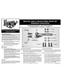
3 Fig. 6 If the cable housing is braided stainless steel, DO NOT remove the ferrule! If the cable housing is black universal, remove the ferrule. Measure the distance between the Kickdown cable adjuster and the Kickdown cable trans bracket. Add 1" to the measurement and cut the cable housing to that American With A Lifetime Warranty!General Installation Notes: Please read these Instructions completely before beginning the Installation . If you have any questions please beginning the Installation , disconnect the negative battery cable and use wheel chocks to block the vehicle's sure the engine, transmission, and frame are properly grounded.
4 We recommend applying anti-seize lubricant to all aluminum threads before final to Fig. 1 and Fig. 2 for the component Kickdown kit is designed to be used with Lokar's Carburetor Bracket and Return Springs, part number 1: Remove the cable end stop, Kickdown throttle body fitting, and Kickdown cable adjuster from the new Lokar Kickdown Cable. Leave the Kickdown mounting bracket on the Kickdown cable adjuster. NOTE: If the cable housing is braided stainless steel, DO NOT REMOVE the ferrule!Step 2: Remove the back cover from the aluminum switch box and remove the slide trigger and inner wire.
5 Fig. 3 Step 3: Mount the aluminum switch box. The aluminum switch box is designed to be mounted to the bottom of the transmission on the left side as shown in Fig. 4, but it can be mounted elsewhere if you like. NOTE: If you are using a Lokar Back-Up Light or Neutral Safety switch (# BL-1400U) or a Lokar Indicator Kit, the aluminum switch box for the Kickdown will have to be mounted elsewhere, since the BL-1400U switch and/or the Indicator cable bracket must be mounted on the left side of the transmission. If mounting the aluminum switch box on the bottom of the transmission, use the provided 5/16"-18 x 1-1/4" bolts with flat washers and spacers.
6 The spacers go between the mounting bracket and the transmission 4: If the throttle cable has already been installed, disconnect the throttle cable from the carburetor. If the engine already has a Lokar Carburetor Bracket installed, leave the bracket in place but remove the throttle cable adjuster from it. If the engine does not already have a Lokar Carburetor Bracket installed, install one now, following the Installation Instructions that are provided with the Lokar Carburetor 5: The Kickdown mounting bracket mounts onto the back side of the Lokar Carburetor Bracket.
7 The throttle cable adjuster will pass through the top hole in both the new Kickdown mounting bracket AND the carburetor FREE 1-877-469-7440 TH400 Electric Kickdown Kit Installation InstructionsTH400 Electric Kickdown Kit Installation InstructionsINS0004 Rev. 05/09/2017 Page 1 2004 Lokar, 6: (Continued) If the Kickdown cable has the braided stainless steel housing, wrap tape around the area to be cut and use a cutoff wheel or fine-toothed hacksaw to cut the cable housing. If the Kickdown cable has the black universal housing, cut the cable housing with heavy duty 8" diagonal cutting pliers or a hacksaw.
8 Lokar recommends Klein brand Diagonal Cutting Pliers, # D2000-28 available at The Home Depot or through W. W. Graingers, Part # 4A838. After cutting the cable housing, put the ferrule back in place at the end of the cable housing. The ferrule does NOT need to be crimped or otherwise attached in place. Insert the cable housing and ferrule into the Kickdown cable 1 Fig. 2 Fig. 3 Cable HousingAllen Wrench (5/64")Cable End StopHex Carb FittingInner WireCable AdjusterCable HousingFerrule(DO NOT REMOVE if Cable Housing is braided stainless steel)
9 Adjuster NutsBack CoverSwitchAluminum switch BoxSlide TriggerKickdown Throttle Body Fitting#10-32 x 1/2" Button Head Bolts with Lock WashersKickdown Mounting Bracket#8-32 x 1/2" Button Head Bolt with Nylock NutLarge Wire TerminalSmall Wire TerminalsAluminum switch Box1/4"-28 x 3/8" Button Head Bolts and Lock WashersKickdown switch Mounting Bracket5/16"-18 x 1-1/4" Hex Head Bolts with Flat Washers and 1/4" SpacersINS0004 Rev. 05/09/2017 Page 2 2004 Lokar, 7: The tear drop (not included, part of the Carburetor Bracket & Spring Kit) will be attached to the carburetor throttle arm by the hex carb fitting.
10 Separate the hex carb fitting from the Kickdown throttle body fitting. Install the hex carb fitting and the tear drop onto the carburetor throttle arm as shown in Fig. 5. Hook the return springs (not included, part of the Carburetor Bracket & Spring kit) to the tear drop. Snug the hex nut down, and then back it off just far enough that the tear drop can rotate 8: Separate the aluminum switch box from the mounting bracket by removing the two 1/4"-28 x 3/8" button head 9: Make sure the spring is still in place on the inner wire, and reinstall the inner wire into the Kickdown cable housing.