Transcription of The 220 MHz All-Mode Transverter - N5DUX
1 Number 8 on your Feedback card THE 220 MHz All-Mode Designed for the dedicated home-brewer. by Robert E. Bloom W6 YUY B ecause of the increased interest and activity in 220 MHz single sideband and the positive response to my Two-Meter Transverter project in July 1987 73 (pps 32- 43), I have now designed an improved, 220 MHz version of the Transverter . This Transverter is capable of FM repeater opera- tion as well as CW and SSB, and it's much more sophisticated than the usual FM transceivers and hand-helds on the market. All frequencies on this unit can be set with direct read-out to the nearest 10 Hz.
2 Of course, DX simplex operation on both FM and SSB is one of its most exciting features. Like the earlier unit, this is an All-Mode Transverter specifically designed to interface with the Kenwood TS-940s HF transceiver. It will also work with other full-frequency coverage transceivers equipped with a Transverter access plug. The Transverter has a CW output of 3-% watts. I will cover in a later article a 220 MHz DMOS linear amplifi- er with a power output of 60 watts. Why Not PC Cards? 'The construction of this unit uses point-to- point wiring in a soldered PC-card structure that provides several benefits.
3 1. A printed circuit board would require foil circuits on both sides, making double-deck construction impossible. 2. Compartmentalizing would require a sepa- rate PC board for each stage or section. 3. A PC card would require more space be- cause of restrictions on parts placement. With this type of construction you can use the walls of the compartment as well as the floor for mounting parts. 4. Exact duplication of components is not required. 5. Excellent interstage isolation. 6. More freedom and ease of modification than normal printed circuit board tech- niques. Your TS-940 transceiver must be modi- fied, of course, to work with the 220 MHz Transverter , because 222 to 225 MHz will be mapped into 22 to 25 MHz and the unmodi- fied transceiver will not transmit outside the ham bands.
4 (Obviously, it is not legal to transmit with the modified Kenwood outside the amateur bands authorized by your class of license.) Take It Step-by-step Realizing the apprehension you may feel when looking at a complex project, I provid- ed, in Figures 5 and 6, drawings of the layout of the major parts. By showing the approxi- mate placement of coils, tuning capacitors, and transistors, I hope to simplify the place- ment of the rest of the components for you. Since you are building this unit step-by-step, you won't have to place the shields between stages in exactly the locations shown in the drawings.
5 Also, your components may be of different sizes, but the compartments should have enough space in most cases. THE HOUSING Case and Module Fabrication The 220 MHz transvelter is a one-piece module with a housing made up of double- sided PC board material. The top of the chas- sis contains the receiver and oscillator chain; the bottom has the transmitter and control circuitry. The outside dimensions of the Transverter assembly are 8- 5/s x 4- 5/4 x 2- 74 ". The height of the partitions is 1/16" less than the depth of the compartment, so the top and bottom cov- ers fit flush with the side panels.
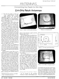
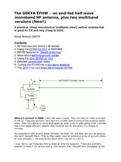
6 Similarly, the front and back panels are % " wider than Figure 1. Schematic ofthe receiver portion of the 222-225 MHz Transverter . 18 73 Amateur Radio 0 January, 1989 TO RELAY RY 3 +VOLTAGE CONTACTS Figure 2. Schematic of crystal oscillator circuit (100 MHz) and doubler. the main circuit board chassis to allow for the 1/16" side panel thickness. Draw a pencil line down the middle of each side piece to help in locating the main center board that separates the top from the bottom. Start by tack-soldering just inside each end, making sure that the sides are at exact right angles with the center board.
7 Then tack the end pieces into position. When the box is square, solder the corners and then seam-sol- der the sides from the inside. Figures 5 and 6 are parts layout drawings showing the individual compartment sizes, f 1/16'' and do not allow for the f 1/16" thick- ness of the separators. These dimensions are flexible and can be used as an indication of how much room you need and how much space you have left as you go along. The compartment separators are also made up of double-sided PC card stock and con- struction is serial: you complete one stage and install a separator before going on to the next stage.
8 This way, you won't be caught either short or long on space. Drill all feedthrough holes in the compartment sepa- rators before soldering the separators in- drilling afterwards is difficult! Single-sided PC stock is used for the termi- nal mounting pads to which component leads are soldered. If all the PC material you have is double-sided, you can remove the foil from one side by holding the material in a bench vise, heating one side gently with a propane torch, and pulling off the foil with pliers. Make up a supply of single-sided strips- l/i ", 5/32", and % ' wide-and snip off pieces as needed with diagonal cutters.
9 Using a sin- gle drop of Eastman 910 cement (Crazy Glue), position these pads where needed with long-nose pliers. Four seconds later, you can solder to the pad. Should you decide that the ' pad is not in exactly the right position, you can remove it by prying with a pocket knife or small sharp screwdriver. Do not re-use a pad, as it will not hold securely the second time. The unit will operate well without the cov- ers in place. However, when the top cover is removed exposing the receiver's pre-selector stages, the unit will pick up strong signals even if it isn't connected to an antenna.
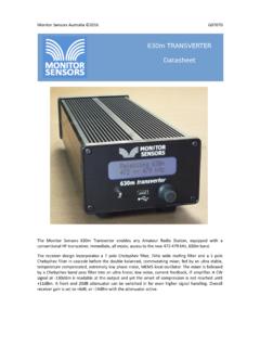
10 Rather than secure the covers permanently, you can hold them in place with transparent tape for easy access to the circuitry. Panel Hardware You can drill the holes in the front and back of the case either before or after the box is JUNCTION VOLTAGE POINTS WITH OTHER AND CONNECT TO CONTlCTS Figure 3. 220 MHz transmitter low-level amplifier section. 73 Amateur Radio January, 1989 19 L-4 L-5 L-6 L-7 L-8 L-9 L-10 L-1 1 L-12 FB Ferrite Beads Q-14-3 Q-4 Q-54-7 220 MHz Receiver Major Components Parts List and Coil Data (Small resistors, capacitors, and inductors not listed) 1-7-pF quality miniature piston capacitors 2-12 pF Johnson air variable, PC board ceramic 3-35 pF ceramic variables Four turns #16 or 18 tinned wire 1/4" inside dia.