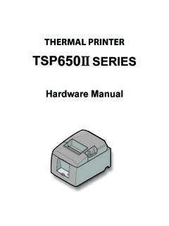
Transcription of THERMAL PRINTER TSP650II SERIES - Star Micronics
1 THERMAL PRINTERTSP650II SERIESH ardware ManualFederal Communications CommissionRadio Frequency InterferenceStatementThis device complies with Part 15 of FCC Rules and Industry Canada licence-exempt RSS standard(s). Operation is subject to the following two conditions: (1) This device may not cause harmful interference, and (2) this device must accept any interference received, including interference that may cause undesired pr sent appareil est conforme aux CNR d'Industrie Canada applicables aux appareils radio exempts de licence. L'exploitation est autoris e aux deux conditions suivantes : (1) l'appareil ne doit pas produire de brouillage, et (2) l'utilisateur de l'appareil doit accepter tout brouillage radio lectrique subi, m me si le brouillage est susceptible d'en compromettre le fonctionnement. FCC CAUTIONC hanges or modifications not expressly approved by the party responsible for compliance could void the user s authority to operate the compliance with the Federal Noise Interference Standard, this equipment requires a shielded RF interference suppression, if a ferrite core is provided with this device, affix it to the interface : This equipment has been tested and found to comply with the limits for a Class A digital device, pursuant to Part 15 of the FCC Rules.
2 These limits are designed to provide reasonable protection against harmful interference when the equipment is operated in a commercial environment. This equipment generates, uses and can radiate radio frequency energy and, if not installed and used in accordance with the instruction manual, may cause harmful interference to radio communications. Operation of this equipment in a residential area is likely to cause harmful interference in which case the user will be required to correct the interference at his own ICES-3 (A) / NMB-3 (A)This equipment complies with FCC/IC radiation exposure limits set forth for an uncontrolled environment and meets the FCC radio frequency (RF) Exposure Guidelines in Supplement C to OET65 and RSS-102 of the IC radio frequency (RF) Exposure rules. This equipment has very low levels of RF energy that it deemed to comply without maximum permissive exposure evaluation(MPE).
3 But it is desirable that it should be installed and operated keeping the radiator at least 20cm or more away from person's body (excluding extremities: hands,wrists,feet and ankles).Cet quipement est conforme aux limites d"exposition aux rayonnements nonc es pour un environnement non contr l et respecte les r gles les radio lectriques (RF) de la FCC lignes directrices d'exposition dans le Suppl ment C OET65 et d"exposition aux fr quences radio lectriques (RF) CNR-102 de l"IC. Cet quipement met une nergie RF tr s faible qui est consid r e conforme sans valuation de l"exposition maximale autoris e. Cependant, cet quipement doit tre install et utilis en gardant une distance de 20 cm ou plus entre le dispositif rayonnant et le corps ( l"exception des extr mit s : mains, poignets, pieds et chevilles). (NCC)(NCC)(NCC)(NCC) Trademark acknowledgmentsTSP650II : Star Micronics Co.
4 , All rights reserved. Reproduction of any part of this manual in any form whatsoever, without STAR s express permission is forbidden. The contents of this manual are subject to change without notice. All efforts have been made to ensure the accuracy of the contents of this manual at the time of going to press. However, should any errors be detected, STAR would greatly appreciate being informed of them. The above notwithstanding, STAR can assume no responsibility for any errors in this manual. IOS is a trademark or registered trademark of Cisco in the and other countries and is used under license. Android is a trademark of Google Inc. Windows is registered trademarks of Microsoft Corporation. Bluetooth wordmark and logo are registered trademarks owned by Bluetooth SIG, Inc. Copyright 2013-2017 Star Micronics Co., SymbolThese symbols are located near the THERMAL print the THERMAL print head is hot immediately after printing, do not touch it.
5 Static electricity can damage the THERMAL print head. To protect the THERMAL print head from static electricity, do not touch symbol is located near the cutter. Never touch the cutter blade, as you could injure your symbol is located near the peripheral drive not connect this to a symbol is located near the screws securing the case or the protective plate, which should not be opened by individuals other than service personnel. Individuals, other than service personnel, should not remove these screws. High voltage areas in the case can be OF CONTENTS 1. Unpacking and Installation ..11-1. Unpacking ..11-2. Notes about Installation ..1 2. Parts Identification and Nomenclature ..2 3. Setup ..33-1. Connecting the Interface Cable to the PC ..33-2. Connecting the Interface Cable to the PRINTER 43-3. Connecting the AC Adapter.
6 73-4. Turning the Power On ..83-5. Connecting to a Peripheral Device ..83-6. Loading a Paper Roll ..93-7. Bluetooth Settings (For Bluetooth Interface Models only) ..123-8. Setup Precautions ..174. Attaching the Accessories ..194-1. Attaching the Holder Plate ..194-2. Attaching the Rubber Feet ..214-3. Switch Cover Installation ..215. Adjusting the Near-end Sensor ..22 6. Error Indicators ..236-1. Recoverable errors ..236-2. Unrecoverable errors ..23 7. Preventing and Removing Paper Jams ..247-1. Preventing Paper Jams ..247-2. Removing Paper Jams ..247-3. Releasing the Cutter Lock ..258. Maintenance ..268-1. THERMAL Head ..268-2. Platen Rubber Roller ..268-3. Paper Holder ..26- 1 - 1. Unpacking and Installation* Accessories vary depending on the model and the region where the PRINTER was rollPrinterHolding plateScrewsSwitch blindSafety Instruction&Setup sheetPaper roll guideRubber feet1-1.
7 UnpackingAfter unpacking the unit, check that all the necessary accessories are included in the Notes about Installation1. Choose a firm, level surface where the PRINTER will not be exposed to Make sure that the PRINTER is connected to a reliable power outlet. It should not be on the same electric circuit as copi-ers, refrigerators, or other appliances that cause power The power outlet you plan to connect to for power should be nearby and Make sure that the PRINTER is not exposed to direct Make sure that the PRINTER is well away from heaters and other sources of extreme Do not locate the PRINTER in a badly ventilated or dusty Make sure that the room where you are using the PRINTER is not too This device employs a DC motor and switches that have an electrical contact point. Avoid using the device in environments where silicon gas can become Use the PRINTER within the boundaries indicated in the environmental requirements.
8 Even when the ambient tem-perature and humidity are within the specifications, avoid radical changes in environmental conditions. The suitable operating temperature range is as follows: Operating temperature: 5 C to 45 C10. When disposing of the PRINTER , obey local 2 -ERRORFEEDPOWERTSP650 2. Parts Identification and NomenclatureControl panelFeatures lamps that indicate PRINTER status and a button for operating the coverOpen to replace not open while switchTurns the PRINTER on and to peripheral devices such as cash not connect this to a tel-ephone drive connectorConnects to an optional AC inletConnects to a host PC through a connectorLights when the PRINTER is lamp also indicates errors, in combination with other lamp (green)Lights when the cover is lamp also indicates errors, in combination with other lamp (red)When the PRINTER is online, pressing this button feeds the paper buttonCover open leverUse this lever to open the PRINTER 3 - 3.
9 Setup3-1. Connecting the Interface Cable to the PC3-1-1. Parallel CableConnect the parallel cable to a parallel port on your RS-232C CableConnect the RS-232C cable to a RS-232C port on your USB CableConnect the USB cable to a USB port on your Ethernet CableConnect the Ethernet cable to a USB port on your 4 -Parallel interface cableFerrite coreInterface cable5 cm(maximum)FastenerPull and cut3-2. Connecting the Interface Cable to the PrinterPrinter cables are not included in the an appropriate cable that complies with the specifications the appropriate interface cable differs depending on the system that you are connecting the PRINTER to, contact the dealer that you bought the product from if you are unsure about what cable to connecting or disconnecting an interface cable, be sure to disconnect the AC adapter s power cord from the Parallel Interface CableTo connect a parallel cable, follow the procedure given below.
10 (1) Make sure the PRINTER is turn off.(2) Affix the ferrite core onto the cable as shown in the illustration.(3) Pass the fastener through the ferrite core.(4) Loop the fastener around the cable and lock it. Use scissors to cut off any excess. (5) Connect the interface cable to the connector on the rear panel of the PRINTER .(6) Fasten the connector 5 -RS-232C interface cableUSB cableCable hook4 cm (maximum)3-2-2. RS-232C Interface Cable(1) Make sure that the AC adapter s power cord is not connected to the outlet.(2) Connect the interface cable to the connector on the rear panel of the PRINTER .(3) Tighten the connector USB CableTo connect a USB cable, follow the procedure given below.(1) Make sure that the AC adapter s power cord is not connected to the outlet.(2) Connect the USB cable to the USB port.(3) As shown in the figure, pass the cable through the cable hooks to hold it in 6 -Ethernet cableIFBD-HE073-2-4.