Transcription of Three-phase short-circuit current (Isc) calculation at any ...
1 Electrical Installation Lecture Dr. Mohammed Tawfeeq Alzuhairi 1 Three-phase short-circuit current (Isc) calculation at any point within a LV installation using impedance method calculation of Isc by the impedance method In a 3-phase installation Isc at any point is given by: where V20 (line-to- line voltage) corresponds to the transformer no-load voltage which is 3 to 5% greater than the on-load voltage across the terminals. For example, in 400 V networks, the line-to-line voltage adopted is V = 420 V and the line -to-neutral voltage is V / 3 = V. Or V20 = line -to- line voltage of the open circuited secondary windings of the power supply transformer(s). ZT = total impedance per phase of the installation upstream of the fault location (in ) Method of calculating ZT Each component of an installation (MV network, transformer, cable, circuit-breaker, bus bar, and so ) is characterized by its impedance Z, comprising an element of resistance (R) and an inductive reactance (X).
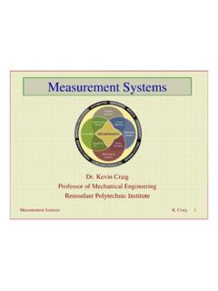
2 It may be noted that capacitive reactances are not important in short-circuit current calculations. The parameters R, X and Z are expressed in ohms, and are related by the sides of a right angled triangle, as shown in the impedance diagram of Figure 1. Impedance diagram Electrical Installation Lecture Dr. Mohammed Tawfeeq Alzuhairi 2 The method consists in dividing the network into convenient sections, and to calculate the R and X values for each. Where sections are connected in series in the network, all the resistive elements in the section are added arithmetically; likewise for the reactances, to give RT and XT. The impedance (ZT) for the combined sections concerned is then calculated from Any two sections of the network which are connected in parallel, can, if predominantly both resistive (or both inductive) be combined to give a single equivalent resistance (or reactance) as follows: Let R1 and R2 be the two resistances connected in parallel, then the equivalent resistance R3 will be given by: or for reactances It should be noted that the calculation of X3 concerns only separated circuit without mutual inductance.
3 If the circuits in parallel are close together the value of X3 will be higher. Determination of the impedance of each component 1- Network upstream of the MV/LV transformer The 3-phase short-circuit fault level PSC, in kA or in MVA(i) is given by the power supply authority concerned, from which an equivalent impedance can be deduced. A formula which makes this deduction and at the same time converts the impedance to an equivalent value at LV is given, as follows: where Zs = impedance of the MV voltage network, expressed in milli-ohms Vo = line-to-line no-load LV voltage, expressed in volts Psc = MV 3-phase short-circuit fault level, expressed in kVA The upstream medium voltage (MV) side resistance Ra is generally found to be negligible compared with the corresponding Xa, the latter then being taken as the ohmic value for Za.
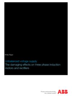
4 If more accurate calculations are Electrical Installation Lecture Dr. Mohammed Tawfeeq Alzuhairi 3 necessary, Xa may be taken to be equal to Za and Ra equal to Xa. Table-1 gives values for Ra and Xa corresponding to the most common MV(ii) short-circuit levels in utility power-supply networks, namely, 250 MVA and 500 MVA. (i) short-circuit MVA: EL Isc where: EL = line -to- line nominal system voltage expressed in kV ( ) Isc = 3-phase short-circuit current expressed in kA ( ) (ii) up to 36 kV Table-1 The impedance of the MV network referred to the LV side of the MV/LV transformer. Psc Vo (V) Ra (m ) Xa (m ) 250 MVA 420 500 MVA 420 2- The Transformer (see Table-2) The impedance Ztr of a transformer, viewed from the LV terminals, is given by the formula: where: V20 = open-circuit secondary line-to- line voltage expressed in volts.
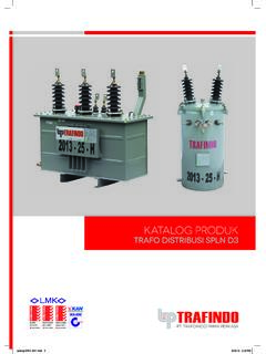
5 Pn = rating of the transformer (in kVA). Vsc = the short-circuit impedance voltage of the transformer expressed in %. The transformer windings resistance Rtr can be derived from the total losses as follows: in milli-ohms where Pcu = total losses in watts In = nominal full-load current in amps Rtr = resistance of one phase of the transformer in milli-ohms (the LV and Electrical Installation Lecture Dr. Mohammed Tawfeeq Alzuhairi 4 corresponding MV winding for one LV phase are included in this resistance value). For an approximate calculation Rtr may be ignored since X Z in standard distribution type transformers. Table -2 : Resistance, reactance and impedance values for typical distribution 400 V transformers with MV windings 20 kV Rated Power (kVA) Oil-immersed Cast-resin Usc (%) Rtr (m ) Xtr (m ) Ztr (m ) Usc (%) Rtr (m ) Xtr (m ) Ztr (m ) 100 4 6 160 4 6 200 4 6 250 4 6 315 4 6 400 4 6 500 4 6 630 4 6 800 6 6 1,000 6 6 1,250 6 6 1,600 6 6 2,000 6 6 3 - Circuit-breakers In LV circuits, the impedance of circuit-breakers upstream of the fault location must be taken into account.
6 The reactance value conventionally assumed is m per CB, while the resistance is neglected. 4 - Busbars The resistance of bus bars is generally negligible, so that the impedance is practically all reactive, and amounts to approximately m / meter length for LV bus bars (doubling the spacing between the bars increases the reactance by about 10% only). Electrical Installation Lecture Dr. Mohammed Tawfeeq Alzuhairi 5 5 - Circuit conductors The resistance of a conductor is given by the formula: where = the resistivity constant of the conductor material at the normal operating temperature being: - m .mm2/m for copper - 36 m .mm2/m for aluminum L = length of the conductor in m S = of conductor in mm2 Table - 3: Values of as a function of the temperature, cable insulation and cable core material, according to IEC60909-0 and Cenelec TR 50480.
7 20 C EPR/XLPE 90 C PVC 70 C Copper Alu L = length of the conductor in m S = of conductor in mm2 Cable reactance values can be obtained from the manufacturers. For of less than 50 mm2 reactance may be ignored. In the absence of other information, a value of m / meter may be used (for 50 Hz systems) or m /meter (for 60 Hz systems). For prefabricated bus-trunking and similar pre-wired ducting systems, the manufacturer should be consulted. 6 - Motors At the instant of short-circuit , a running motor will act (for a brief period) as a generator, and feed current into the fault. In general, this fault- current contribution may be ignored. However, if the total power of motors running simultaneously is higher than 25% of the total power of transformers, the influence of motors must be taken into account.
8 Their total contribution can be estimated from the formula: Iscm = In from each motor (m In) for m similar motors operating concurrently. The motors concerned will be the 3-phase motors only; single-phase-motor contribution being insignificant. Electrical Installation Lecture Dr. Mohammed Tawfeeq Alzuhairi 6 7 - Fault-arc resistance short-circuit faults generally form an arc which has the properties of a resistance. The resistance is not stable and its average value is low, but at low voltage this resistance is sufficient to reduce the fault- current to some extent. Experience has shown that a reduction of the order of 20% may be expected.
9 This phenomenon will effectively ease the current -breaking duty of a CB, but affords no relief for its fault- current making duty. Example 1: For the installation Network shown in make short circuit calculation from MV take-off point to the final distribution board. Assume all cables are XLPE type. Solution: The short circuit current Is given by 1-To calculate the short circuit current at LV B/B -1,The total Impedance ZT from point A to point B must be found . Network upstream of the MV/LV transformer From Table 1 ,for short-circuit level of 500 MVA. Electrical Installation Lecture Dr.
10 Mohammed Tawfeeq Alzuhairi 7 Ra = (m ) , Xa = (m ) The Transformer : from table -2 , for 1000kVA rating , Rtr = (m ) , Xtr = (m ) For the single-core cables 5 m copper 4 x 240 mm2/phase : From Table -3: Let the cable type XLPE , = approx.,hence, L = 5 m and S = 4x240 mm2, therefore , (m ) Xc = x 5 = (m ) [ Cable reactance values can be obtained from the manufacturers. For of less than 50 mm2 reactance may be ignored. In the absence of other information, a value of m / metre may be used (for 50 Hz systems)] For the main circuit breaker: R and X are Not considered in practice. Now from point A to point B , RT1 = Ra + Rtr + Rc = + + = (m ) XT1= Xa+ Xtr + Xc = + + = (m ) 2 Short circuit calculation at point C: Bus bar B/B1,10 m , Not considered in practice.


![A arXiv:2108.00154v1 [cs.CV] 31 Jul 2021](/cache/preview/5/1/4/3/3/e/9/d/thumb-51433e9dee8472b1576151350bb9b5bc.jpg)