Transcription of TPSMA6L Series Pb e3 - littelfuse.com
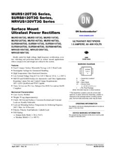
1 TVS Diodes 2016 littelfuse , are subject to change without notice. Revised: 09/10/16 Surface Mount 600W > TPSMA6L seriesDescriptionFeaturesMaximum Ratings and Thermal Characteristics (TA=25OC unless otherwise noted)ParameterSymbolValueUnitPeak Pulse Power Dissipation at TA=25 C by 10x1000 s Waveform ( )(Note 1), (Note 2) PPPM600 WPower Dissipation on Infinite Heat Sink at TA=50 OCPM(AV)3 WPeak Forward Surge Current, Single Half Sine Wave (Note 3)IFSM60 AMaximum Instantaneous Forward Voltage at 25A for Unidirectional Only Junction and Storage Temperature RangeTJ, TSTG-65 to 150 CTypical Thermal Resistance Junction to LeadRuJL35 C/WTypical Thermal Resistance Junction to AmbientRuJA200 C/WNotes:1.
2 Non-repetitive current pulse, per and derated above TA=25 C per Fig. Mounted on copper pad to each Measured on single half sine wave or equivalent square wave for unidirectional device TPSMA6L Series is designed specifically to protect sensitive electronic equipment from voltage transients induced by load dump and other transient voltage events, and it s especially suitable for high reliability and automotive application. SMA low profile package (DO221-AC) has the same electronical performance as the SMB package but with low height profiles ( ).ApplicationsTVS devices are ideal for the protection of I/O Interfaces, VCC bus and other vulnerable circuits used in Telecom, Computer, Industrial and Consumer electronic applications.
3 Same power as standard SMB devices (600 W) Hi reliability application and automotive grade AEC Q101 qualified SMA low profile package: less than mm Footprint compatibility with standard SMA and SMB products (easy to layout) Typical failure mode is short from over-specified voltage or current Whisker test is conducted based on JEDEC JESD201A per its table 4a and 4c IEC-61000-4-2 ESD 15kV(Air), 8kV (Contact) ESD protection of data lines in accordance with IEC 61000-4-2 EFT protection of data lines in accordance with IEC 61000-4-4 Low inductance, excellent clamping capability Fast response time.
4 Typically less than from 0 Volts to VBR min Built-in strain relief Glass passivated junction High temperature soldering: 260 C/10 seconds at terminals Plastic package has underwriters laboratory flammability V-0 Typical maximum temperature coefficient VBR = x VBR@25 C x T Matte tin lead free plated Halogen free and RoHS compliant Pb-free E3 means 2nd level interconnect is Pb-free and the terminal finish material is tin(Sn) (IPC/JEDEC ) TPSMA6L SeriesFunctional DiagramBi-directional Uni-directional Cathode AnodeUni-directionalRoHSe3 PbAgency ApprovalsAGENCYAGENCY FILE NUMBERE230531 TVS Diodes 2016 littelfuse , are subject to change without notice.
5 Revised: 09/10/16 Surface Mount 600W > TPSMA6L seriesElectrical CharacteristicsPart Number (Uni)MarkingReverse Stand off Voltage VR (Volts)Breakdown Voltage VBR (Volts) @ ITTest CurrentIT (mA)Maximum Clamping Voltage VC @ Ipp (V)Maximum Peak Pulse Current Ipp (A)Maximum Reverse Leakage IR @ VR( A)Agency ApprocalMINMAX 1011. 0X 11 7. 7. Diodes 2016 littelfuse , are subject to change without notice. Revised: 09/10/16 Surface Mount 600W > TPSMA6L seriesI-V Curve CharacteristicsVcVBRVRIRITIppVUni-direct ionalVFPPPM Peak Pulse Power Dissipation -- Max power dissipation VR Stand-off Voltage -- Maximum voltage that can be applied to the TVS without operationVBR Breakdown Voltage -- Maximum voltage that flows though the TVS at a specified test current (IT)VC Clamping Voltage -- Peak voltage measured across the suppressor at a specified Ippm (peak impulse current)
6 IR Reverse Leakage Current -- Current measured at VRVF Forward Voltage Drop for Uni-directional Width (ms.) " ( )Copper Pad AreaPPPM-Peak Pulse Power (kW)Figure 2 - Peak Pulse Power Rating CurveVoltage TransientsTimeVoltage Across TVSC urrent Through TVSV oltage or CurrentFigure 1 - TVS Transients Clamping WaveformRatings and Characteristic Curves (TA=25 C unless otherwise noted)continues on next Diodes 2016 littelfuse , are subject to change without notice. Revised: 09/10/16 Surface Mount 600W > TPSMA6L series0204060801000255075100125175 Peak Pulse Power (PPP) or Current (IPP)Derating in Percentage %150TJ - Initial Junction Temperature ( C) (pF)Tj=25 Cf= V=0 VUni-directional @VRVBR - Reverse Breakdown Voltage (V)Figure 3 - Pulse Derating CurveIPPM- Peak Pulse Current, % IRSM005010 01501.
7 SecPeak ValueIPPMIPPM2TJ=25 CPulse Width(td) is definedas the point where the peak current decays to 50% of IPPM10/1000 sec. Waveformas defined by (ms)Half ValueIPPM( )Figure 4 - Pulse WaveformFigure 5 - Typical Junction Capacitance0255075100125150175PM(AV), Steady State Power Dissipation (W)TA - Ambient Te mperature ( C)bargaini ng C/WFigure 6 - Steady State Power Dissipation Derating CurveRatings and Characteristic Curves (TA=25 C unless otherwise noted) (Continued)TVS Diodes 2016 littelfuse , are subject to change without notice. Revised: 09/10/16 Surface Mount 600W > TPSMA6L seriesDimensionsPhysical ounce, gramCaseJEDEC DO-221AC Molded Plastic over glass passivated junctionPolarity Color band denotes cathode except BipolarTerminalMatte Tin-plated leads, Solderable per 10 0 Environmental SpecificationsSoldering ParametersTemperature (T)Time (t)Ts(min)Ts(max)TLTPtsPreheattLtpRamp-u pCritical ZoneTL to TPRamp-downt 25 C to Peak25 CReflow ConditionLead free assemblyPre Heat- Temperature Min (Ts(min))150 C - Temperature Max (Ts(max))200 C- Time (min to max) (ts)
8 60 180 secsAverage ramp up rate (Liquidus Temp (TL) to peak3 C/second maxTS(max) to TL - Ramp-up Rate3 C/second maxReflow- Temperature (TL) (Liquidus)217 C - Time (min to max) (ts)60 150 secondsPeak Temperature (TP)260+0/-5 CTime within 5 C of actual peak Temperature (tp)20 40 secondsRamp-down Rate6 C/second maxTime 25 C to peak Temperature (TP)8 minutes not exceed260 ( ) ( )1. 52 ( )Mounting Pad LayoutABEECGFC athode BandHigh Temp. StorageJESD22-A103 HTRBJESD22-A108 Temperature CyclingJESD22-A104 MSLJEDEC-J-STD-020, Level 1H3 TRBJESD22-A101 RSHJESD22-A111 TVS Diodes 2016 littelfuse , are subject to change without notice.)
9 Revised: 09/10/16 Surface Mount 600W > TPSMA6L seriesPart Numbering SystemPart Marking SystemPackagingPart numberComponent Package QuantityPackaging OptionPackaging SpecificationTPSMA6 LxxADO-221AC3000 Tape & Reel 12mm/7 tapeEIA RS-481 TPSMA6L xx ASERIES5% VBR VOLTAGE TOLERANCE VR VOLTAGETape and Reel ( ) ( ) ( ) ( ) ( ) Arbor Hole (178) Dimensions are in inches(and millimeters).Direction of DIA( )Cover tapeCathodeFXXXYMXXXM arking CodeTrace Code Marking Y:Year Code M: Month Code XXX: Lot CodeLittelfuse LogoCathode Ba