Transcription of MURS120T3 - MURS120T3G Series, SURS8120T3G Series ...
1 MURS120T3G Series , SURS8120T3G Series , nrvus120vt3g Series Surface Mount Ultrafast Power Rectifiers MURS105T3G, MURS110T3G, MURS115T3G, MURS120T3G , MURS140T3G, MURS160T3G, ULTRAFAST RECTIFIERS. SURS8105T3G, SURS8110T3G, SURS8115T3G, AMPERE, 50 600 VOLTS. SURS8120T3G , SURS8140T3G, SURS8160T3G, NRVUS110VT3G, nrvus120vt3g , NRVUS160VT3G. Ideally suited for high voltage, high frequency rectification, or as SMB. free wheeling and protection diodes in surface mount applications CASE 403A. where compact size and weight are critical to the system. MARKING DIAGRAM. Features Small Compact Surface Mountable Package with J Bend Leads AYWW. Rectangular Package for Automated Handling U1x G. High Temperature Glass Passivated Junction G. Low Forward Voltage Drop ( to V Max @ A, TJ = 150 C).
2 NRVUS and SURS8 Prefixes for Automotive and Other Applications A =. Assembly Location*. Y =. Year Requiring Unique Site and Control Change Requirements;. WW =. Work Week AEC Q101 Qualified and PPAP Capable U1 =. Device Code These Devices are Pb Free, Halogen Free/BFR Free and are RoHS x = A, B, C, D, G, or J. Compliant G = Pb Free Package (Note: Microdot may be in either location). Mechanical Characteristics: * The Assembly Location code (A) is front side Case: Epoxy, Molded optional. In cases where the Assembly Location is stamped in the package bottom (molding ejecter Weight: 95 mg (Approximately) pin), the front side assembly code may be blank. Finish: All External Surfaces Corrosion Resistant and Terminal Leads are Readily Solderable ORDERING INFORMATION. Lead and Mounting Surface Temperature for Soldering Purposes: See detailed ordering and shipping information in the table on 260 C Max.
3 For 10 Seconds page 2 of this data sheet. Polarity: Polarity Band Indicates Cathode Lead ESD Rating: DEVICE MARKING INFORMATION. Human Body Model = 3B (> 8 kV) See general marking information in the device marking table on page 2 of this data sheet. Machine Model = C (> 400 V). Semiconductor Components Industries, LLC, 2017 1 Publication Order Number: April, 2017 Rev. 15 MURS120T3 /D. MURS120T3G Series , SURS8120T3G Series , nrvus120vt3g Series MAXIMUM RATINGS. MURS/SURS8/NRVUS. Rating Symbol 105T3 110T3 115T3 120T3 140T3 160T3 Unit Peak Repetitive Reverse Voltage VRRM 50 100 150 200 400 600 V. Working Peak Reverse Voltage VRWM. DC Blocking Voltage VR. Average Rectified Forward Current IF(AV) @ TL = 155 C @ TL = 150 C A. @ TL = 145 C @ TL = 125 C. Non Repetitive Peak Surge Current, (Surge applied IFSM 40 35 A.)
4 At rated load conditions halfwave, single phase, 60 Hz). Operating Junction Temperature TJ *65 to +175 C. Stresses exceeding those listed in the Maximum Ratings table may damage the device. If any of these limits are exceeded, device functionality should not be assumed, damage may occur and reliability may be affected. THERMAL CHARACTERISTICS. MURS/SURS8/NRVUS. Rating Symbol 105T3 110T3 115T3 120T3 140T3 160T3 Unit Thermal Resistance RqJL C/W. Junction to Lead (TL = 25 C) 13. ELECTRICAL CHARACTERISTICS. Maximum Instantaneous Forward Voltage (Note 1) vF V. (iF = A, TJ = 25 C) (iF = A, TJ = 150 C) Maximum Instantaneous Reverse Current (Note 1) iR mA. (Rated DC Voltage, TJ = 25 C) (Rated DC Voltage, TJ = 150 C) 50 150. Maximum Reverse Recovery Time trr ns (iF = A, di/dt = 50 A/ms) 35 75.
5 (iF = A, iR = A, IR to A) 25 50. Maximum Forward Recovery Time tfr ns (iF = A, di/dt = 100 A/ms, Rec. to V) 25 50. Typical Peak Reverse Recovery Current IRM A. (IF = A, di/dt = 50 A/ms). Product parametric performance is indicated in the Electrical Characteristics for the listed test conditions, unless otherwise noted. Product performance may not be indicated by the Electrical Characteristics if operated under different conditions. 1. Pulse Test: Pulse Width = 300 ms, Duty Cycle v DEVICE MARKING AND ORDERING INFORMATION. Device Marking Package Shipping . MURS105T3G, U1A SMB 2,500 Units / Tape & Reel SURS8105T3G* (Pb Free). MURS110T3G, NRVUS110VT3G* U1B SMB 2,500 Units / Tape & Reel SURS8110T3G* (Pb Free). MURS115T3G, SURS8115T3G* U1C SMB 2,500 Units / Tape & Reel (Pb Free).
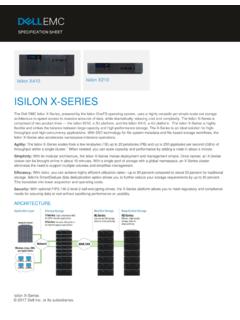
6 MURS120T3G , nrvus120vt3g * U1D SMB 2,500 Units / Tape & Reel SURS8120T3G * (Pb Free). MURS140T3G, SURS8140T3G*, U1G SMB 2,500 Units / Tape & Reel (Pb Free). MURS160T3G, NRVUS160VT3G* U1J SMB 2,500 Units / Tape & Reel SURS8160T3G* (Pb Free). For information on tape and reel specifications, including part orientation and tape sizes, please refer to our Tape and Reel Packaging Specifications Brochure, BRD8011/D. *NRVUS and SURS8 Prefixes for Automotive and Other Applications Requiring Unique Site and Control Change Requirements; AEC Q101. Qualified and PPAP Capable. 2. MURS120T3G Series , SURS8120T3G Series , nrvus120vt3g Series MURS105T3G, MURS110T3G, MURS115T3G, MURS120T3G , SURS8105T3G, SURS8110T3G, SURS8115T3G, SURS8120T3G , NRVUS110VT3G, nrvus120vt3g . 10 80. 40 TJ = 175 C.
7 20. IR, REVERSE CURRENT (m A). TJ = 100 C. 175 C 100 C i , INSTANTANEOUS FORWARD CURRENT (AMPS). TJ = 25 C. TC = 25 C. 0 20 40 60 80 100 120 140 160 180 200. VR, REVERSE VOLTAGE (VOLTS). Figure 2. Typical Reverse Current*. *The curves shown are typical for the highest voltage device in the voltage grouping. Typical reverse current for lower voltage selections can be estimated from these same curves if applied VR is sufficiently below rated VR. 50. F. 45. 40 NOTE: TYPICAL. CAPACITANCE AT. C, CAPACITANCE (pF). 35 0 V = 45 pF. 30. 25. 20. 15. 10. 0. vF, INSTANTANEOUS VOLTAGE (VOLTS) 0 10 20 30 40 50 60 70 80 90 100. Figure 1. Typical Forward Voltage VR, REVERSE VOLTAGE (VOLTS). Figure 3. Typical Capacitance PF(AV) , AVERAGE POWER DISSIPATION (WATTS). 10. IF(AV) , AVERAGE FORWARD CURRENT (AMPS).
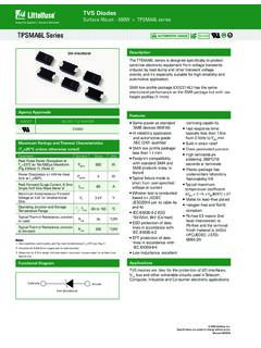
8 RATED VOLTAGE APPLIED TJ = 175 C. RqJC = 13 C/W. TJ = 175 C I 10. (CAPACITANCE LOAD) PK + 20. I. AV. DC. DC. SQUARE WAVE. SQUARE WAVE. 0 0. 80 90 100 110 120 130 140 150 160 170 180 0 TC, CASE TEMPERATURE ( C) IF(AV), AVERAGE FORWARD CURRENT (AMPS). Figure 4. Current Derating, Case Figure 5. Power Dissipation 3. MURS120T3G Series , SURS8120T3G Series , nrvus120vt3g Series MURS140T3G, MURS160T3G, SURS8140T3G, SURS8160T3G, NRVUS160VT3G. 10 400. 200. 80 TJ = 175 C. IR, REVERSE CURRENT (m A). 175 C 40. 20. 100 C TJ = 100 C. TC = 25 C i , INSTANTANEOUS FORWARD CURRENT (AMPS). TJ = 25 C. 0 100 200 300 400 500 600 700. VR, REVERSE VOLTAGE (VOLTS). Figure 7. Typical Reverse Current*. *The curves shown are typical for the highest voltage device in the voltage grouping. Typical reverse current for lower voltage selections can be estimated from these same curves if applied VR is sufficiently below rated VR.
9 25. F. 20 NOTE: TYPICAL. CAPACITANCE AT. C, CAPACITANCE (pF). 0 V = 24 pF. 15. 10. 0. vF, INSTANTANEOUS VOLTAGE (VOLTS) 0 12 16 20 24 28 32 36 40. Figure 6. Typical Forward Voltage VR, REVERSE VOLTAGE (VOLTS). Figure 8. Typical Capacitance PF(AV) , AVERAGE POWER DISSIPATION (WATTS). 10. IF(AV) , AVERAGE FORWARD CURRENT (AMPS). (CAPACITANCE LOAD) 10 RATED VOLTAGE APPLIED. RqJC = 13 C/W I. PK + 20 SQUARE WAVE. TJ = 175 C I. AV. DC. TJ = 175 C. DC. SQUARE WAVE. 0 0. 0 20 40 60 80 100 120 140 160 180 200 0 TC, CASE TEMPERATURE ( C) IF(AV), AVERAGE FORWARD CURRENT (AMPS). Figure 9. Current Derating, Case Figure 10. Power Dissipation 4. MURS120T3G Series , SURS8120T3G Series , nrvus120vt3g Series PACKAGE DIMENSIONS. SMB. CASE 403A 03. ISSUE J. HE. NOTES: 1. DIMENSIONING AND TOLERANCING PER ANSI , 1982.
10 E 2. CONTROLLING DIMENSION: INCH. 3. DIMENSION b SHALL BE MEASURED WITHIN DIMENSION L1. MILLIMETERS INCHES. DIM MIN NOM MAX MIN NOM MAX. A b D A1 b c D E POLARITY INDICATOR HE OPTIONAL AS NEEDED. L L1 REF REF. A. A1. L L1 c SOLDERING FOOTPRINT*. SCALE 8:1 inches mm . *For additional information on our Pb Free strategy and soldering details, please download the ON Semiconductor Soldering and Mounting Techniques Reference Manual, SOLDERRM/D. ON Semiconductor and are trademarks of Semiconductor Components Industries, LLC dba ON Semiconductor or its subsidiaries in the United States and/or other countries. ON Semiconductor owns the rights to a number of patents, trademarks, copyrights, trade secrets, and other intellectual property. A listing of ON Semiconductor's product/patent coverage may be accessed at ON Semiconductor reserves the right to make changes without further notice to any products herein.