Transcription of ULN2003 LINEAR INTEGRATED CIRCUIT
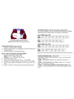
1 UNISONIC TECHNOLOGIES CO., LTD ULN2003 LINEAR INTEGRATED CIRCUIT 1 of 10 Copyright 2018 Unisonic Technologies Co., Ltd 7CH DARLINGTON SINK DRIVER DESCRIPTION The UTC ULN2003 are high-voltage, high-current darlington drivers comprised of seven NPN Darlington pairs. All units feature integral clamp diodes for switching inductive loads. Applications include relay, hammer, lamp and display (LED)drivers. FEATURES *Output Current (Single Output): 500mA (Max.)
2 *High Sustaining Voltage Output: 50V (Min.) *Output Clamp Diodes *Inputs Compatible With Various Types Of Logic ORDERING INFORMATION Ordering Number Lead Free Halogen Free Package Packing ULN2003L-D16-T ULN2003G-D16-T DIP-16 Tube ULN2003L-S16-R ULN2003G-S16-R SOP-16 Tape Reel ULN2003L-P16-R ULN2003G-P16-R TSSOP-16 Tape
3 Reel MARKING DIP-16 SOP-16 / TSSOP-16 ULN2003 LINEAR INTEGRATED CIRCUIT UNISONIC TECHNOLOGIES CO., LTD 2 of 10 PIN CONNECTION BLOCK DIAGRAM Note: The input and output parasitic diodes cannot be used as clamp diodes.
4 ULN2003 LINEAR INTEGRATED CIRCUIT UNISONIC TECHNOLOGIES CO., LTD 3 of 10 ABSOLUTE MAXIMUM RATINGS (TA=25 C, unless otherwise specified) PARAMETER SYMBOLRATING UNIT Output Sustaining Voltage VOUT ~ 50 V Input Voltage VIN ~ 30 V Clamp Diode Reverse Voltage VR 50 V Output Current IOUT 500 mA / chClamp Diode Forward Current IF 500 mA DIP-16
5 W SOP-16 (Note2) W Power Dissipation TSSOP-16 PD W Junction Temperature TJ +150 C Operating Temperature TOPR -40 ~ +85 C Storage Temperature TSTG -55 ~ +150 C Notes: 1.
6 Absolute maximum ratings are those values beyond which the device could be permanently damaged. Absolute maximum ratings are stress ratings only and functional device operation is not implied. 2. On PCB (Test Board: JEDEC 2s2p) RECOMMENDED OPERATING CONDITIONS (TA=-40~+85 C, unless otherwise specified) CHARACTERISTIC SYMBOLTEST CONDITIONS MIN TYP MAXUNITO utput Sustaining Voltage VOUT 0 50 V Duty=10% 0 350 DIP-16 Duty=50% 0 100 Duty=10% 0 300 SOP-16 Duty=50% 0 90 Duty=10% 0 150 Output Current TSSOP-16 IOUT TPW = 25ms7
7 Circuits TA = 85 C TJ = 120 CDuty=50% 0 30 mA/chInput Voltage VIN 0 24 V Input Voltage (Output On) VIN (ON) IOUT = 400mA 24 V Input Voltage (Output Off) VIN (OFF) 0 Clamp Diode Reverse Voltage VR 50 V Clamp Diode Forward Current IF 350mADIP-16 TA = 85 C TA = 85 C (Note) Dissipation TSSOP-16 PD TA = 85 C Note: On PCB (Test Board: JEDEC 2s2p) ULN2003 LINEAR INTEGRATED CIRCUIT UNISONIC TECHNOLOGIES CO.
8 , LTD 4 of 10 ELECTRICAL CHARACTERISTICS (TA=25 C, unless otherwise specified) CHARACTERISTIC SYMBOL TEST CIRCUITTEST CONDITIONS MIN TYP MAX UNITVCE=50V, TA=25 C 50 Output Leakage Current ILEAK 1 VCE=50V, TA=85 C 100 AIOUT=350mA, IIN=500 A , IIN=350 A Saturation Voltage VCEO(SAT)
9 2 IOUT=100mA, IIN=250 A DC Current Transfer Ratio hFE 2 VCE=2V, IOUT=350mA 1000 Input Current (Output On) IIN (ON) 3 VIN= , IOUT=350mA Current (Output Off) IIN (OFF) 4 IOUT=500 A, TA=85 C 50 65 AIOUT = 350 mA Voltage (Output On) VIN(ON)
10 5 VCE=2V IOUT = 200 mA VR=50V, TA=25 C 50 Clamp Diode Reverse Current IR 6 VR=50V, TA=85 C 100 AClamp Diode Forward Voltage VF 7 IF=350mA Input Capacitance CIN 15 pFTurn-On Delay tON 8 VOUT=50V.