Transcription of Understanding Boost Power Stages in Switchmode Power …
1 UnderstandingBoostPowerStagesinSwitchmod ePowerSuppliesMarch 1999 Mixed Signal ProductsApplicationReportSLVA061 IMPORTANT NOTICET exas Instruments and its subsidiaries (TI) reserve the right to make changes to their products or to discontinueany product or service without notice, and advise customers to obtain the latest version of relevant informationto verify, before placing orders, that information being relied on is current and complete. All products are soldsubject to the terms and conditions of sale supplied at the time of order acknowledgement, including thosepertaining to warranty, patent infringement, and limitation of warrants performance of its semiconductor products to the specifications applicable at the time of sale inaccordance with TI s standard warranty.
2 Testing and other quality control techniques are utilized to the extentTI deems necessary to support this warranty. Specific testing of all parameters of each device is not necessarilyperformed, except those mandated by government APPLICATIONS USING SEMICONDUCTOR PRODUCTS MAY INVOLVE POTENTIAL RISKS OFDEATH, PERSONAL INJURY, OR SEVERE PROPERTY OR ENVIRONMENTAL DAMAGE ( CRITICALAPPLICATIONS ). TI SEMICONDUCTOR PRODUCTS ARE NOT DESIGNED, AUTHORIZED, ORWARRANTED TO BE SUITABLE FOR USE IN LIFE-SUPPORT DEVICES OR SYSTEMS OR OTHERCRITICAL APPLICATIONS. INCLUSION OF TI PRODUCTS IN SUCH APPLICATIONS IS UNDERSTOOD TOBE FULLY AT THE CUSTOMER S order to minimize risks associated with the customer s applications, adequate design and operatingsafeguards must be provided by the customer to minimize inherent or procedural assumes no liability for applications assistance or customer product design.
3 TI does not warrant or representthat any license, either express or implied, is granted under any patent right, copyright, mask work right, or otherintellectual property right of TI covering or relating to any combination, machine, or process in which suchsemiconductor products or services might be or are used. TI s publication of information regarding any thirdparty s products or services does not constitute TI s approval, warranty or endorsement 1999, Texas Instruments Incorporatediii Understanding Boost Power StagesContents1 Introduction1.. 2 Boost Power Stage Steady-State Analysis2.. Boost Steady-State Continuous Conduction Mode Analysis2.
4 Boost Steady-State Discontinuous Conduction Mode Analysis7.. Critical Inductance10.. 3 Boost Power Stage Modeling12.. Boost Continuous Conduction Mode Small-Signal Analysis13.. Boost Discontinuous Conduction Mode Small-Signal Analysis16.. 4 Component Selection19.. Output Capacitance19.. Output Inductance20.. Power Switch21.. Output Diode22.. 5 Example Design24.. 6 Summary25.. 7 References27.. FiguresivSLVA061 List of Figures1 Boost Power Stage Schematic2.. 2 Boost Power Stage States3.. 3 Continuous Mode Boost Power Stage Waveforms4.. 4 Boundary Between Continuous and Discontinuous Mode7.. 5 Discontinuous Current Mode8.
5 6 Discontinuous Mode Boost Power Stage Waveforms10.. 7 Power Supply Control Loop Components12.. 8 Boost Nonlinear Power Stage Gain vs. Duty Cycle13.. 9 DC and Small Signal CCM PWM Switch Model14.. 10 CCM Bost Power Stage Model14.. 11 Averaged (Nonlinear) DCM PWM Switch Model16.. 12 DCM Boost Power Stage DC Model17.. 13 Small Signal DCM Boost Power Stage Model18.. 1 Understanding Boost Power Stagesin Switchmode Power SuppliesEverett RogersABSTRACTA switching Power supply consists of the Power stage and the control circuit. The powerstage performs the basic Power conversion from the input voltage to the output voltageand includes switches and the output filter.
6 This report addresses the Boost Power stageonly and does not cover control circuits. The report includes detailed steady-state andsmall-signal analysis of the Boost Power stage operating in continuous and discontinuousmodes. A discussion of Power stage component requirements is IntroductionThe three basic switching Power supply topologies in common use are the buck, Boost , and buck- Boost . These topologies are non-isolated, , the input andoutput voltages share a common ground. There are however, isolated derivationsof these non-isolated topologies. The Power supply topology refers to how theswitches, output inductor, and output capacitor are connected.
7 Each topologyhas unique properties, including the steady-state voltage conversion ratios, thenature of the input and output currents, and the character of the output voltageripple. Another important property is the frequency response of theduty-cycle-to-output-voltage transfer Boost is a popular non-isolated Power stage topology, sometimes called astep-up Power stage. Power supply designers choose the Boost Power stagebecause the required output voltage is always higher than the input voltage, isthe same polarity, and is not isolated from the input. The input current for a boostpower stage is continuous, or non-pulsating, because the input current is thesame as the inductor current.
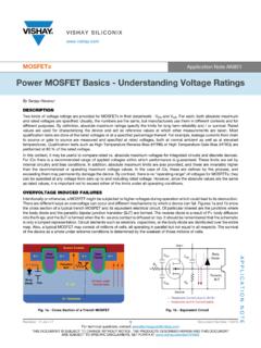
8 The output current for a Boost Power stage isdiscontinuous, or pulsating, because the output diode conducts only during aportion of the switching cycle. The output capacitor supplies the entire loadcurrent for the rest of the switching application report describes steady-state operation and gives idealwaveforms for the Boost converter in continuous and discontinuous modes. Theduty-cycle-to-output-voltage transfer function is given using the PWM 1 shows a simplified schematic of the Boost Power stage with a drive circuitblock included. Power switch Q1 is an n-channel MOSFET. The output diode isCR1. Inductor L and capacitor C make up the effective output filter.
9 The capacitorequivalent series resistance (ESR), RC, and the inductor dc resistance, RL, areincluded in the analysis. Resistor R represents the load seen by the Power Power Stage Steady-State Analysis2 SLVA061acpIL = icRC+VIDriveCircuitCR1 LCRQ1 VOiasgdRLFigure 1. Boost Power Stage SchematicDuring normal operation of the Boost Power stage, Q1 is repeatedly switched onand off with the on and off times governed by the control circuit. This switchingaction creates a train of pulses at the junction of Q1, CR1, and L. Althoughinductor L is connected to output capacitor C only when CR1 conducts, aneffective L/C output filter is formed. It filters the train of pulses to produce a dcoutput voltage, VO.
10 The following sections give a more detailed Boost Power Stage Steady-State AnalysisA Power stage can operate in continuous or discontinuous inductor current continuous inductor current mode, current flows continuously in the inductorduring the entire switching cycle in steady-state operation. In discontinuousinductor current mode, inductor current is zero for a portion of the switching starts at zero, reaches a peak value, and returns to zero during each switchingcycle. The two modes are discussed in greater detail later, and design guidelinesare given for the inductor value to maintain a chosen mode of operation as afunction of rated load.