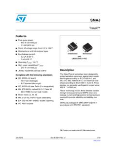
Transcription of Unidirectional Bidirectional SMB (JEDEC DO-214AA)
1 January 2018 DocID5616 Rev 11 1/11 This is information on a product in full production. SMBJ Transil Datasheet - production data Features Peak pulse power: 600 W (10/1000 s) 4 kW (8/20 s) Stand-off voltage range: from 5 V to 188 V Unidirectional and Bidirectional types Low leakage current: A at 25 C 1 A at 85 C Operating Tj max: 150 C High power capability at Tj max: 515 W (10/1000 s) JEDEC registered package outlineComplies with the following standards IEC 61000-4-2 level 4: 15 kV (air discharge) 8 kV (contact discharge) IEC 61000-4-5 MIL STD 883G, method 3015-7.
2 Class 3B: 25 kV HBM (human body model) Resin meets UL 94, V0 MIL-STD-750, method 2026 soldererability EIA STD RS-481 and IEC 60286-3 packing IPC 7531 footprintDescription The SMBJ Transil series has been designed to protect sensitive equipment against electrostatic discharges according to IEC 61000-4-2, and MIL STD 883, method 3015, and electrical over stress according to IEC 61000-4-4 and 5. These devices are more generally used against surges below 600 W (10/1000 s). Planar technology makes these devices suitable for high-end equipment and SMPS where low leakage current and high junction temperature are required to provide reliability and stability over time.
3 SMBJ are packaged in SMB (SMB footprint in accordance with IPC 7531 standard). Transil is a trademark of STMicroelectronics. KAUnidirectionalBidirectionalSMB (JEDEC DO-214AA) KACharacteristics SMBJ 2/11 DocID5616 Rev 11 1 Characteristics Table 1: Absolute maximum ratings (Tamb = 25 C) Symbol Parameter Value Unit PPP Peak pulse power dissipation Tj initial = Tamb 600 W Tj Operating junction temperature range -55 to +150 C Tstg Storage temperature range -65 to +150 C TL Maximum lead temperature for soldering during 10 s 260 C Table 2.
4 Thermal resistance Symbol Parameter Value Unit Rth(j-l) Junction to leads 20 C/W Rth(j-a) Junction to ambient on printed circuit on recommended pad layout 100 C/W Figure 1: Electrical characteristics - parameter definitions Figure 2: Pulse definition for electrical characteristics SMBJ Characteristics DocID5616 Rev 11 3/11 Table 3: Electrical characteristics parameter values (Tamb = 25 C, unless otherwise specified) Order code IRM max at VRM VBR at IR(1) 10 / 1000 s 8 / 20 s T(2) VCL IPP RD VCL IPP RD 25 C 85 C Min.
5 Typ. Max. Max. Max. Max. A V V mA V(3) A(4) V A 10-4/ C 20 50 10 68 275 20 50 10 61 270 20 50 10 56 266 20 50 1 205 SMBJ10A/CA 1 10 1 17 37 184 SMBJ12A/CA 1 12 1 31 157 SMBJ13A/CA 1 13 1 29 147 SMBJ15A/CA 1 15 1 123 SMBJ16A/CA 1 16 1 26 116 SMBJ18A/CA 1 18 1 102 SMBJ20A/CA 1 20 1 93 SMBJ22A/CA 1 22 1 83 SMBJ24A/CA 1 24 1 16
6 50 80 SMBJ26A/CA 1 26 1 75 SMBJ28A/CA 1 28 1 59 68 SMBJ30A/CA 1 30 1 13 62 SMBJ33A/CA 1 33 1 57 SMBJ36A/CA 1 36 1 76 52 SMBJ40A/CA 1 40 1 84 48 SMBJ48A/CA 1 48 1 100 40 SMBJ58A/CA 1 58 1 121 33 SMBJ70A/CA 1 70 1 113 146 27 SMBJ85A/CA 1 85 94 99 1 137 178 SMBJ100A/CA 1 100 111 117 1 162 212 19 SMBJ130A/CA 1 130 144 152 1 209 3 265 15 SMBJ154A/CA 1 154 171 180 1 246 317 SMBJ170A/CA 1 170 189 199 1 275 353 SMBJ188A/CA 1 188 209 220 1 328 2 388 Notes: (1)Pulse test: tp < 50 ms (2)To calculate VBR or VCL versus junction temperature, use the following formulas: VBR at TJ = VBR at 25 C x (1 + T x (TJ - 25)) VCL at TJ = VCL at 25 C x (1 + T x (TJ-25)) (3)To calculate maximum clamping voltage at other surge level, use the following formula.
7 VCLmax = VBR max + RD x IPPappli where IPPappli is the surge current in the application Characteristics SMBJ 4/11 DocID5616 Rev 11 (4)Surge capability given for both directions for Unidirectional and Bidirectional types. Characteristics (curves) Figure 3: Peak pulse power dissipation versus initial junction temperature Figure 4: Peak pulse power versus exponential pulse duration (Tamb = 25 C) Figure 5: Clamping voltage versus peak pulse current (exponential waveform, maximum values) 0100200300400500600700025507510012515017 5 Ppp(W)Tj( C) + +01 PPP(kW)Tjinitial = 25 CtP(ms)IPP( A ) sTjinitial=25 C8/20 s10 msS M B J5.
8 0 AS M B J188 AS M B J1 2 AS M B J24 AS M B J40 AS M B J85 AS M B J5 .0 AS M B J188 AS M B J1 2 AS M B J24 AS M B J40 AS M B J85 AVCL(V)SMBJ Characteristics DocID5616 Rev 11 5/11 Figure 6: Junction capacitance versus reverse applied voltage (typical values) (SMBJxxA) Figure 7: Junction capacitance versus reverse applied voltage (typical values) (SMBJxxCA) Figure 8: Peak forward voltage drop versus peak forward current (typical values) Figure 9: Relative variation of thermal impedance junction to ambient versus pulse duration Figure 10.
9 Thermal resistance junction to ambient versus copper surface under each lead (printed circuit board FR4, eCu = 35 m) Figure 11: Leakage current versus junction temperature (typical values) 101001000100001101001000C(pF)F=1 MHzVosc=30 mVRMSTj=25 (V)101001000100001101001000C(pF)F=1 MHzVosc=30 mVRMSTj=25 (V)IFM(A) + + + CTj=125 CVFM(V) + + + +03 Zth(j-a)/ Rth(j-a)tP(s)Recommended pad layoutPCB FR4, copper thickness = 35 (j-a)( C/W)(printed ci rc uit boa rd FR4,copper thic knes s = 35 m)SCu(cm )IR(nA) + + + +03255075100125150VR=VRMVRM 10 VVR=VRMVRM< 10 VT ( C)
10 JPackage information SMBJ 6/11 DocID5616 Rev 11 2 Package information In order to meet environmental requirements, ST offers these devices in different grades of ECOPACK packages, depending on their level of environmental compliance. ECOPACK specifications, grade definitions and product status are available at: ECOPACK is an ST trademark. Case: JEDEC DO214-AA molded plastic over planar junction Terminals: solder plated, solderable per MIL-STD-750, method 2026 Polarity: for Unidirectional types the band indicates cathode.