Transcription of UNISONIC TECHNOLOGIES CO., LTD
1 UNISONIC TECHNOLOGIES CO., LTD ULN2803 LINEAR INTEGRATED CIRCUIT 1 of 6 Copyright 2019 UNISONIC TECHNOLOGIES Co., Ltd EIGHT DARLINGTON ARRAYS DESCRIPTION The UTC ULN2803 is high-voltage, high-current Darlington drivers comprised of eight NPN Darlington pairs. FEATURES *Output current (single output) 500mA MAX. *High sustaining voltage output 50V MIN. *Output clamp diodes *Inputs compatible with various types of logic SOP-18 DIP-18 SOP-20 TSSOP-20 QFN-20(4 4)1 ORDERING INFORMATION Ordering Number Package Packing Lead Free Halogen Free ULN2803L-D18-T ULN2803G-D18-T DIP-18 Tube ULN2803L-S18-R ULN2803G-S18-R SOP-18 Tape Reel ULN2803L-S20-R ULN2803G-S20-R SOP-20 Tape Reel ULN2803L-P20-R ULN2803G-P20-R TSSOP-20 Tape Reel ULN2803G-Q20-4040-R ULN2803G-Q20-4040-R QFN-20(4 4) Tape Reel ULN2803G-D18-T(1)Packing Type(2)Package Type(3)Green Package(1) T: Tube, R.
2 Tape Reel(2) D18: DIP-18, S18: SOP-18, S20: SOP-20 P20: TSSOP-20, Q20-4040: QFN-20(4 4)(3) G: Halogen Free and Lead Free, L: Lead Free MARKING DIP-18 SOP-18 UTC ULN2803123456789101112131415 Date CodeLot Code161718L: Lead FreeG: Halogen Free UTC ULN2803 1234567891011121314 Date CodeLot Code15161718L: Lead FreeG: Halogen Free SOP-20 / TSSOP-20 QFN4040-20 UTC ULN280312345678910111213141516 Date CodeLot Code17181920L: Lead FreeG: Halogen Free UTCULN2803 Date CodeLot Code ULN2803 LINEAR INTEGRATED CIRCUIT UNISONIC TECHNOLOGIES CO.
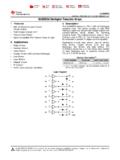
3 , LTD 2 of 6 PIN CONFIGURATIONS ININININININININGNDOUTOUTOUTOUTOUTOUTOUT OUTCOMMON FREE WHEELING DIODES181716151413121110123456789 DIP-18/SOP-18 SOP-20/TSSOP-20 ININININININININGNDOUTOUTOUTOUTOUTOUTOUT OUTCOMMON FREE WHEELING DIODES1918171615141312112345678910 NCNC2012IN1IN2 OUT5431111213155 OUT7 OUT7IN6IN3IN5IN161819206 OUT67810 GNDTop View8 OUT8 INGND1 OUT179 COM2144IN4 OUT3 OUTQFN4040-20 NCNC SCHEMATICS (EACH DRIVER) 3k Note: The input and output parasitic diodes cannot be used as clamp diodes.
4 ULN2803 LINEAR INTEGRATED CIRCUIT UNISONIC TECHNOLOGIES CO., LTD 3 of 6 ABSOLUTE MAXIMUM RATINGS PARAMETER SYMBOL RATINGS UNIT Input Voltage VIN ~30 V Output Sustaining Voltage VCE (SUS) ~50 V Output Current IOUT 500 mA/ch Clamp Diode Reverse Voltage VR 50 V Clamp Diode Forward Current IF 500 mA Power Dissipation DIP-18 PD W SOP-18 (Note)
5 W SOP-20 W TSSOP-20 W QFN4040-20 W Operating Temperature TOPR -40 ~ +85 C Storage Temperature TSTG -40 ~ +150 C Notes: 1. On glass epoxy PCB ( Cu 50%) 2. Absolute maximum ratings are stress ratings only and functional device operation is not implied. The device could be damaged beyond Absolute maximum ratings. ELECTRICAL CHARACTERISTICS (TA=25 C, unless otherwise specified) PARAMETER SYMBOL TEST CIRCUIT TEST CONDITIONS MIN TYP MAX UNIT Output Leakage Current ICEX 1 VCE=50V,TA=25 C VCE=50V,TA=85 C 50 100 A Collector-Emitter Saturation Voltage VCE(SAT) 2 IOUT=350mA,IIN=500 A IOUT=200mA,IIN=350 A IOUT=100mA,IIN=250 A V Input Current ON IIN(ON) 3 VIN = , IOUT=350mA mA OFF IIN(OFF) 4 IOUT=500 A, TA=85 C 50 65 A Input Voltage (output on) VIN(ON)
6 5 VCE= IOUT=200mA IOUT=250mA IOUT=300mA V Clamp Diode Reverse Current IR 6 VR=50V, TA=25 C VR=50V, TA=85 C 50 100 A Clamp Diode Forward Voltage VF 7 IF=350mA V Input Capacitance CIN 15 25 pF Turn-On Delay tON 8 VOUT=50V,RL=125 ,CL=15pF 1 S Turn-Off Delay tOFF 8 VOUT=50V,RL=125 ,CL=15pF 1 S ULN2803 LINEAR INTEGRATED CIRCUIT UNISONIC TECHNOLOGIES CO., LTD 4 of 6 TEST CIRCUIT OPENICEXOPENVCEVIN1.
7 ICEXOPENIOUTIINVCE, VCE (sat)hFE = IOUTIIN2. VCE (sat), hFEOPENIIN (ON)VIN3. IIN (ON)OPENIOUT4. IIN (OFF)OPENIOUTIINVCE5. VIN (ON)OPEN6. IROPENIIN (OFF)VIN (ON)VRIRIF7. VFVFOPENOPENIOUT 8. tON, tOFF RLPULSE GENERATOROPENVOUTOUTPUTINPUT(Note 2)(Note 1)CL = 15pF(Note 3)VIH0 VOHVOL tftr90%50%10%90%10%50%tON50 s50%50%tOFFINPUTOUTPUT Notes: 1. Pulse width 50 s, duty cycle 10% Output impedance 50 , tr<=5ns, tf<=10ns 2. R1: 0, VIH: 3V 3. CL includes probe and jig capacitance. ULN2803 LINEAR INTEGRATED CIRCUIT UNISONIC TECHNOLOGIES CO.
8 , LTD 5 of 6 TYPICAL CHARACTERISTICS IIN VINI nput Voltage, VIN (V) Input Current, IIN (mA) VINI nput Voltage, VIN (V) Input Current, IIN (mA)12400102030200408TA=25 CIOUT = 100mA300 IOUT IINI nput Current, IIN ( A) Output Current, IOUT (mA)40030020010000100200300400500TA=75 CVCE = 2V2530600 RecommendedMaximum RatingIF VFClamp Diode Forward Voltage, VF (V)Clamp Diode Forward Current, IF (mA) = 25 - IOUTO utput Current, IOUT (mA)DC Current Transfer Ration, hFE1000010001000010100100010000500030005 0030050301085 C-40 C25 CVCE = TAAmbient Temperature, TA ( C)Power Dissipation, PD (W) free airSOP-18 on glass epoxy PCB30 30 Cu 50%SOP-18 free airSOP-20 free airTSSOP-20 free ULN2803 LINEAR INTEGRATED CIRCUIT UNISONIC TECHNOLOGIES CO.
9 , LTD 6 of 6 UTC assumes no responsibility for equipment failures that result from using products at values that exceed, even momentarily, rated values (such as maximum ratings, operating condition ranges, or other parameters) listed in products specifications of any and all UTC products described or contained herein. UTC products are not designed for use in life support appliances, devices or systems where malfunction of these products can be reasonably expected to result in personal injury.
10 Reproduction in whole or in part is prohibited without the prior written consent of the copyright owner. UTC reserves the right to make changes to information published in this document, including without limitation specifications and product descriptions, at any time and without notice. This document supersedes and replaces all information supplied prior to the publication hereof.