Transcription of UNISONIC TECHNOLOGIES CO., LTD
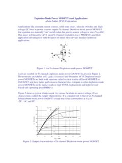
1 UNISONIC TECHNOLOGIES CO., LTD tl431 LINEAR INTEGRATED CIRCUIT 1 of 6 Copyright 2018 UNISONIC TECHNOLOGIES Co., Ltd PROGRAMMABLE PRECISION REFERENCE DESCRIPTION The UTC tl431 is a three-terminal adjustable regulator with a guaranteed thermal stability over applicable temperature ranges. The output voltage may be set to any value between VREF (approximately ) and 36V with two external resistors. It provides very wide applications, including shunt regulator, series regulator, switching regulator, voltage reference and others.
2 FEATURES * Programmable output Voltage to 36V. * Low dynamic output impedance . * Sink current capability of to 100mA. * Equivalent full-range temperature coefficient of 50ppm/ C typical for operation over full rated operating temperature range. ORDERING INFORMATION Ordering Number Pin Assignment Lead Free Halogen Free Package 123456 7 8 Packing TL431K-AB3-R TL431G-AB3-R SOT-89 RAK--- - - Tape ReelTL431K-AE2-R TL431G-AE2-R SOT-23-3 KRA--- - - Tape ReelTL431K-AE3-R TL431G-AE3-R SOT-23 KRA--- - - Tape ReelTL431 NSL-AE3-R tl431 NSG-AE3-R SOT-23 RKA--- - - Tape ReelTL431 NSL-AE2-R tl431 NSG-AE2-R SOT-23-3 RKA.
3 Tape ReelTL431 NSL-AH3-R tl431 NSG-AH3-R TSOT-23 RKA--- - - Tape ReelTL431K-AF5-R TL431G-AF5-R SOT-25 XXKRA- - - Tape ReelTL431K-AF5-B-R TL431G-AF5-B-R SOT-25 XAXKR - - - Tape ReelTL431K-AF5-C-R TL431G-AF5-C-R SOT-25 RAKXX- - - Tape ReelTL431K-S08-R TL431G-S08-R SOP-8 KAAXXA A R Tape ReelTL431K-K03-K TL431G-G03-K SIP-3 RAK--- - - Bulk TL431K-T92-B TL431G-T92-B TO-92 RAK--- - - Tape Box TL431K-T92-K TL431G-T92-K TO-92 RAK--- - - Bulk Note: Pin Code: K: Cathode A: Anode R: Reference X: No Connection tl431 LINEAR INTEGRATED CIRCUIT UNISONIC TECHNOLOGIES CO.
4 , LTD 2 of 6 MARKING PACKAGE MARKING PACKAGE MARKING SOT-23-3 SOT-23 ( tl431 ) SOP-8 SOT-23-3 SOT-23 TSOT-23 (TL431NS) SIP-3 SOT-25 SOT-25 (Pin B, C) SOT-89 TO-92 PIN CONFIGURATION (For SOP-8) BLOCK DIAGRAM VREFCATHODEANODEREFERENCECATHODE (K)ANODE(A)REFERENCE (R) tl431 LINEAR INTEGRATED CIRCUIT UNISONIC TECHNOLOGIES CO., LTD 3 of 6 ABSOLUTE MAXIMUM RATINGS (Operating temperature range applies, unless otherwise specified) PARAMETER SYMBOL RATINGS UNIT Cathode Voltage VKA 37 V Cathode Current Range(Continuous)
5 IKA -100 ~ +150 mA Reference Input Current Range IREF ~ +10 mA TO-92 770 mW SOT-89 800 mW SOT-23/SOT-23-3 TSOT-23/SOT-25300 mW SIP-3 400 mW Power Dissipation SOP-8 PD 600 mW Operating Junction TJ +150 C Operating Ambient (Note 2) TOPR -40 ~ +125 C Storage Temperature TSTG -65 ~ +150 C Notes.
6 1. Absolute maximum ratings are those values beyond which the device could be permanently damaged. Absolute maximum ratings are stress ratings only and functional device operation is not implied. 2. It is guarantee by design, not 100% be tested. RECOMMENDED OPERATING CONDITIONS PARAMETER SYMBOL MIN TYP MAX UNIT Cathode Voltage VKA VREF 36 V Cathode Current IKA 1 100 mA ELECTRICAL CHARACTERISTICS (TC= 25 C, unless otherwise specified.)
7 PARAMETER SYMBOLTEST CONDITIONS MIN TYP MAX UNITTL431-A ( ) tl431 -1 ( 1%) tl431 -2 (+2%) - Reference Input Voltage VREF VKA=VREF, IKA=10mA tl431 -3 (-2%) - Deviation of reference Input Voltage Over temperature T VREFVKA=VREF,IKA=10mA, 0 C TA 70 C 17mV VKA=10V~VREF mV/VRatio of Change in Reference Input Voltage to the Change in Cathode Voltage KAREF V VIKA=10mA VKA=36V~10V mV/VReference Input Current IREF IKA=10mA, R1=10k , R2= 4 ADeviation of Reference Input Current Over Full Temperature Range T IREFIKA=10mA, R1=10k , R2=.
8 TA =full Temperature AMinimum Cathode Current for Regulation IKA(MIN)VKA=VREF Cathode Current IKA(OFF)VKA=36V, VREF=0 ADynamic Impedance ZKA VKA=VREF, IKA=1~ 100mA,f tl431 LINEAR INTEGRATED CIRCUIT UNISONIC TECHNOLOGIES CO., LTD 4 of 6 TEST CIRCUIT INPUTVKAVREFIKAUTC tl431 VKA=VREF (1+R1/R2)+IREF R1 For VKA=VREF For VKA VREF For IKA(OFF) APPLICATION CIRCUIT VOUT=(1+R1/R2) VREF VOUT=(1+R1/R2) VREF Minimum VOUT=VREF+5V VOUT=(1+R1/R2) VREF Shutdown Regulator Output Control of a Three -Terminal Fixed Regulator Higher-current Shunt Regulator UTC tl431 RSVOUTVINIOUT UTC tl431 RSIOUTVINVOUTRCL IOUT=VREF/RS IOUT =VREF/RCL Constant-current Sink Current Limiting or Current Source tl431 LINEAR INTEGRATED CIRCUIT UNISONIC TECHNOLOGIES CO.
9 , LTD 5 of 6 TYPICAL CHARACTERISTICS -11023-2000400200600800-2 Cathode Voltage (V)Cathode Current ( A)0123456701234567 Time ( s)Input and Output Voltage (V)Pulse ResponseTA=25 C Change In Reference Input Voltage (mV)TA=25 CVKA=VREFC hange in Reference Input Voltage Voltage Cathode Current vs. Cathode VoltageIKA(MIN)0510152025303540-1-1 Cathode Voltage (V)-2-10123-100-75-50-250255075100125 Cathode Voltage (V)Cathode Current (mA)Cathode Current vs. Cathode Voltage150TA=25 CVKA=VREF0-5-10-15-20-25-30-35-40 IKA=10mATA=25 C tl431 LINEAR INTEGRATED CIRCUIT UNISONIC TECHNOLOGIES CO.
10 , LTD 6 of 6 UTC assumes no responsibility for equipment failures that result from using products at values that exceed, even momentarily, rated values (such as maximum ratings, operating condition ranges, or other parameters) listed in products specifications of any and all UTC products described or contained herein . UTC products are not designed for use in life support appliances, devices or systems where malfunction of these products can be reasonably expected to result in personal injury. Reproduction in whole or in part is prohibited without the prior written consent of the copyright owner.