Transcription of Universal Asynchronous Receiver Transmitter (UART)
1 2009-2013 Microchip Technology 1 HIGHLIGHTSThis section of the manual contains the following major .. Registers .. Baud Rate Generator .. Configuration .. Transmitter .. Bit Detection .. Receiver .. the UART for 9-Bit Communication .. Features of the UART .. UART Operation with DMA .. UART Operation During CPU Sleep and Idle Modes .. Operation of UxCTS and UxRTS Control Pins .. Infrared Support .. LIN/J2602 Support .. Smart Card Support .. Registers Related Application Revision History .. 53 Universal Asynchronous Receiver Transmitter (UART)dsPIC33/PIC24 Family Reference ManualDS70000582E-page 2 2009-2013 Microchip Technology document supersedes the following PIC24 and dsPIC Family Reference Manual Universal Asynchronous Receiver Transmitter (UART) module is one of the serial I/Omodules available in the dsPIC33 and PIC24 device families.
2 The UART is a full-duplex, Asynchronous communication channel that communicates with peripheral devices and personalcomputers, using protocols such as RS-232, RS-485, LIN/J2602 and IrDA . The module alsosupports the hardware flow control option with the UxCTS and UxRTS pins and includes the IrDAencoder and primary features of the UART module are as follows: Full-duplex, 8-bit or 9-bit data transmission through the UxTX and UxRX pins Even, odd or no parity options (for 8-bit data) One or two Stop bits Hardware auto-baud feature Hardware flow control option with the UxCTS and UxRTS pins (These pins are not available on all devices. Refer to the Universal Asynchronous Receiver Transmitter (UART) chapter of the specific device data sheet for availability.) Fully integrated Baud Rate Generator (BRG) with 16-bit prescaler Baud rates up to Mbps Four-deep First-In First-Out (FIFO) transmit data buffer Four-deep FIFO receive data buffer Parity, framing and buffer overrun error detection Support for 9-bit mode with address detect (9th bit = 1) Transmit and receive interrupts Loopback mode for diagnostic support IrDA encoder and decoder logic LIN/J2602 bus support ( and ) 16x baud clock output for external IrDA encoder/decoder support Optional ISO 7816 Smart Card supportNote:This family reference manual section is meant to serve as a complement to devicedata sheets.
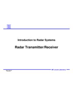
3 Depending on the device variant, this manual section may not apply toall dsPIC33 and PIC24 consult the note at the beginning of the Universal AsynchronousReceiver Transmitter (UART) chapter in the current device data sheet to checkwhether this document supports the device you are data sheets and family reference manual sections are available for downloadfrom the Microchip worldwide web site at: NumberSection NumberTitleDS3970821 UART: PIC24F Family Reference Manual DS70232 17 UART: PIC24H Family Reference Manual DS7058217 UART: dsPIC33E/PIC24E Family Reference Manual DS70066 19, 34 UART: dsPIC30F Family Reference ManualDS70188 17 UART: dsPIC33F/PIC24H Family Reference ManualDS70582 17 UART: dsPIC33E/PIC24E Family Reference Manual 2009-2013 Microchip Technology 3 UARTA simplified block diagram of the UART is illustrated in Figure 1-1.
4 The UART module consistsof the following key hardware elements : Baud Rate Generator Asynchronous Transmitter Asynchronous ReceiverFigure 1-1:UARTx Simplified Block DiagramBaud Rate GeneratorUxRXHardware Flow ControlUARTx ReceiverUARTx TransmitterUxTXUxCTSUxRTSBCLKxISO 7816 SupportIrDA dsPIC33/PIC24 Family Reference ManualDS70000582E-page 4 2009-2013 Microchip Technology REGISTERSThis section outlines the specific functions of each register that controls the operation of theUART module: UxMODE: UARTx Mode Register- Enables or disables the UART module- Enables or disables the IrDA encoder and decoder- Enables or disables the WAKE, ABAUD bits and Loopback features- Enables or disables the UxRTS and UxCTS pins - Configures the UxRTS pin for the desired mode of operation- Configures the polarity of the UxRX pin- Selects the type of baud rate- Selects the number of data bits, parity and Stop bits UxSTA: UARTx Status and Control Register- Selects the Transmission Interrupt mode- Selects the Receive Interrupt mode- Enables or disables the UART transmission- Controls the Address Detect mode- Indicates various status conditions, such as transmit and receive buffer state, parity error, framing error and overflow error UxADMD.
5 UARTx Address Mask Detect Register- Stores address match and mask values UxRXREG: UARTx Receive Register- Stores the received data UxTXREG: UARTx Transmit Register (Write-Only)- Provides the data to be transmitted UxBRG: UARTx Baud Rate Register- Stores the baud rate value of the transmitted or received dataNote:Each dsPIC33/PIC24 family device variant may have one or more UART x used in the names of pins, control/status bits and registers denotes the par-ticular UART module number. Refer to the Universal Asynchronous ReceiverTransmitter (UART) chapter of the specific device data sheet for more details. 2009-2013 Microchip Technology 5 UARTR egister 2-1:UxMODE: UARTx Mode RegisterR/W-0U-0R/W-0R/W-0R/W-0R/W-0R/W- 0R/W-0 UARTEN(3) USIDLIREN(1)RTSMDALTIO(2)UEN1(2)UEN0(2)b it 15bit 8R/W-0R/W-0R/W-0R/W-0R/W-0R/W-0R/W-0R/W- 0 WAKE(4)LPBACKABAUD(5)URXINVBRGHPDSEL1 PDSEL0 STSELbit 7bit 0 Legend:R = Readable bitW = Writable bitU = Unimplemented bit, read as 0 -n = Value at POR 1 = Bit is set 0 = Bit is clearedx = Bit is unknownbit 15 UARTEN: UARTx Enable bit(3)1 = UARTx is enabled; UARTx pins are controlled by UARTx as defined by the UEN<1:0> andUTXEN control bits0 = UARTx is disabled.
6 UARTx pins are controlled by the corresponding PORTx, LATx and TRISx bitsbit 14 Unimplemented: Read as 0 bit 13 USIDL: UARTx Stop in Idle Mode bit1 = Discontinues operation when the device enters Idle mode0 = Continues operation in Idle modebit 12 IREN: IrDA Encoder and Decoder Enable bit(1)1 = IrDA encoder and decoder are enabled0 = IrDA encoder and decoder are disabledbit 11 RTSMD: Mode Selection for UxRTS Pin bit1 = UxRTS is in Simplex mode0 = UxRTS is in Flow Control modebit 10 ALTIO: UARTx Alternate I/O Selection bit(2)1 = UARTx communicates using UxATX and UxARX I/O pins0 = UARTx communicates using UxTX and UxRX I/O pinsbit 9-8 UEN<1:0>: UARTx Enable bits(2)11 = UxTX, UxRX and BCLKx pins are enabled and used; UxCTS pin is controlled by port latches10 = UxTX, UxRX, UxCTS and UxRTS pins are enabled and used01 = UxTX, UxRX and UxRTS pins are enabled and used; UxCTS pin is controlled by port latches00 = UxTX and UxRX pins are enabled and used; UxCTS, UxRTS and BCLKx pins are controlled byport latchesbit 7 WAKE: Enable Wake-up on Start bit Detect During Sleep Mode bit(4)1 = Wake-up is enabled0 = Wake-up is disabledbit 6 LPBACK: UARTx Loopback Mode Select bit1 = Enables Loopback mode0 = Loopback mode is disabledNote 1:This feature is only available for Standard Speed mode (BRGH = 0).
7 Refer to the Universal Asynchronous Receiver Transmitter (UART) chapter of the specific device data sheet for :These features may not be available on all devices. Refer to the Universal Asynchronous Receiver Transmitter (UART) chapter of the specific device data sheet for :Enable this bit before enabling the UTXEN bit (UxSTA<10>).4:The UARTx module does not recognize the first character received on a :The use of this feature may consume the corresponding Input Capture x (ICx) peripheral. See Section Auto-Baud Support for more Family Reference ManualDS70000582E-page 6 2009-2013 Microchip Technology 5 ABAUD: Auto-Baud Enable bit(5)1 = Enables baud rate measurement on the next character, requires reception of a Sync field (0x55);cleared in hardware upon completion0 = Baud rate measurement is disabled or completebit 4 URXINV: UARTx Receive Polarity Inversion bit1 = UxRX Idle state is 0 0 = UxRX Idle state is 1 bit 3 BRGH: High Baud Rate Select bit1 = BRG generates 4 clocks per bit period (4x baud clock, High-Speed mode)0 = BRG generates 16 clocks per bit period (16x baud clock, Standard Speed mode)bit 2-1 PDSEL<1:0>: Parity and Data Selection bits11 = 9-bit data, no parity10 = 8-bit data, odd parity01 = 8-bit data, even parity00 = 8-bit data, no paritybit 0 STSEL: Stop Selection bit1 = 2 Stop bits0 = 1 Stop bitRegister 2-1:UxMODE: UARTx Mode Register (Continued)Note 1:This feature is only available for Standard Speed mode (BRGH = 0).
8 Refer to the Universal Asynchronous Receiver Transmitter (UART) chapter of the specific device data sheet for :These features may not be available on all devices. Refer to the Universal Asynchronous Receiver Transmitter (UART) chapter of the specific device data sheet for :Enable this bit before enabling the UTXEN bit (UxSTA<10>).4:The UARTx module does not recognize the first character received on a :The use of this feature may consume the corresponding Input Capture x (ICx) peripheral. See Section Auto-Baud Support for more information. 2009-2013 Microchip Technology 7 UARTR egister 2-2:UxSTA: UARTx Status and Control RegisterR/W-0R/W-0R/W-0R/W-0R/W-0R/W-0R- 0R-1 UTXISEL1 UTXINVUTXISEL0 URXEN(1)UTXBRK UTXEN(2)UTXBFTRMT(3)bit 15bit 8R/W-0R/W-0R/W-0R-1R-0R-0R/C-0R-0 URXISEL1 URXISEL0 ADDENRIDLEPERRFERROERRURXDAbit 7bit 0 Legend:C = Clearable bitR = Readable bitW = Writable bitU = Unimplemented bit, read as 0 -n = Value at POR 1 = Bit is set 0 = Bit is clearedx = Bit is unknownbit 15,13 UTXISEL<1:0>.
9 UARTx Transmission Interrupt Mode Selection bits11 = Reserved10 = Interrupt is generated when a character is transferred to the Transmit Shift Register (TSR) andthe transmit buffer becomes empty01 = Interrupt is generated when the last transmission is over, transmit buffer is empty ( , the lastcharacter has been shifted out of the Transmit Shift Register) and all the transmit operations arecompleted00 = Interrupt is generated when any character is transferred to the Transmit Shift Register and thetransmit buffer is empty (which implies at least one location is empty in the transmit buffer)bit 14 UTXINV: UARTx Transmit Polarity Inversion bitIREN = 0:1 = UxTX Idle state is 0 0 = UxTX Idle state is 1 IREN = 1:1 = IrDA is encoded, UxTX Idle state is 1 0 = IrDA is encoded, UxTX Idle state is 0 bit 12 URXEN: UARTx Receive Enable bit(1)1 = Receive is enabled, UxRX pin is controlled by UARTx0 = Receive is disabled, UxRX pin is controlled by the portbit 11 UTXBRK: UARTx Transmit Break bit1 = UxTX pin is driven low regardless of the Transmitter state (Sync Break transmission Start bit isfollowed by twelve 0 s and a Stop bit)0 = Sync Break transmission is disabled or completebit 10 UTXEN: UARTx Transmit Enable bit(2)1 = UARTx Transmitter is enabled; UxTX pin is controlled by UARTx (if UARTEN = 1)0 = UARTx Transmitter is disabled; any pending transmission is aborted and the buffer is reset, UxTXpin is controlled by the portbit 9 UTXBF: UARTx Transmit Buffer Full Status bit (read-only)1 = Transmit buffer is full0 = Transmit buffer is not full.
10 At least one more data word can be writtenbit 8 TRMT: Transmit Shift Register is Empty bit (read-only)(3)1 = Transmit Shift Register is empty and the transmit buffer is empty ( , the last transmission hascompleted)0 = Transmit Shift Register is not empty; a transmission is in progress or queued in the transmit bufferNote 1:This bit is only available in devices supporting Smart Card. Refer to the Universal Asynchronous Receiver Transmitter (UART) chapter of the specific device data sheet for :Enable the UARTEN bit (UxMODE<15>) before enabling this :User software should wait at least one instruction cycle between writing UxTXREG and reading the TRMT Family Reference ManualDS70000582E-page 8 2009-2013 Microchip Technology 7-6 URXISEL<1:0>: UARTx Receive Interrupt Mode Selection bits11 = Interrupt flag bit is set when the receive buffer is full ( , 4 data characters)10 = Interrupt flag bit is set when the receive buffer is 3/4 full ( , 3 data characters)0x = Interrupt flag bit is set when a character is receivedbit 5 ADDEN: Address Character Detect bit (bit 8 of received data = 1)1 = Address Detect mode is enabled.