Transcription of Using Acoustic Beamforming for Pass-By Noise …
1 1. NATIONA L INSTRU MEN TS. A PPLIC ATI O N N OTES. Using Acoustic Beamforming for Pass-By Noise Source Detection Abstract This application note discusses a technique known as Beamforming for determining Noise location of passing vehicles. The technique has several challenges including simultaneous acquisition of a large sensor array, advanced signal processing and storage of extremely large data sets, and the environmental considerations required for operating outdoors on a test track. This application note recommends best practices for performing Beamforming and walks through the complete system required from the test environment to the sensors to the math, analysis, and data storage with the goal of the reader being able to apply the technique.
2 Doug Farrell Product Manager, national instruments Introduction to Acoustic 2. Acoustic Beamforming System 4. Environmental Considerations on Test 4. Microphone Arrays for Acoustic 5. Wiring Considerations for Microphone 6. Signal Conditioning and Data Acquisition for Microphone 7. Signal Processing and Analysis for Acoustic Displaying Noise Source 12. Data 13. Additional 14. 14. Introduction to Acoustic Beamforming Traditional Pass-By Noise tests are useful for determining the sound level of Noise sources on a vehicle during operation. These are often measured to ensure compliance with local and federal laws that govern acceptable sound emitted from a vehicle to produce minimal traffic Noise .
3 Pass-By Noise source identification takes this one step further by identifying the source of the Noise as well, so engineers can fine-tune vehicle design to minimize Noise . You can use several analysis techniques to identify Noise sources including near-field Acoustic holography (NAH) and Beamforming . NAH operates in a More Than Vehicles sound's so-called near field, within one or two wavelengths of the source, This same technique can be applied to more where sound waves act as circular waves emanating from the source. than just automobiles.
4 Boeing has used Acoustic Beamforming , on the other hand, is more suited to the far field, located at Beamforming to help locate and reduce Noise roughly seven wavelengths from the Noise source, where sound waves act on its aircraft, and the Korean Railroad Research as planar waves [1]. If you can think of a sound source like a pebble falling in Institute has used it to reduce Noise emissions water, then sound emanating from the source is like the waves that come on its high-speed KTX trains. from where the pebble hit. When you are close to where the pebble fell, the waves are clearly in a circle, centered on where the pebble fell.
5 If you are standing far away on the shore, however, the waves no longer look like circles but just a straight line coming toward you. Sound waves behave in the same way. Because measurement sensors can often not be close enough to passing vehicles to be in the near field and perform NAH, Beamforming is the preferred technique for Noise location in such applications. Source Source . Figure 1. Sound waves in the near field (A) move away from the source in a circular pattern. In the far field (B), they are far enough away from the source that they appear to move in a straight line.
6 Beamforming presents several challenges including simultaneously measuring a large number of microphone sensors, transmitting and saving this large amount of acquired waveform data, and being able to quickly process large data sets to visualize the results in real time. This application note strives to offer the best techniques for performing Beamforming on passing objects and provide guidance so that the end result is an accurate analysis of Noise location and volume on vehicles. In creating this application note, the author used NI cDAQ-9178 and NI 9234 C Series hardware to perform the data acquisition and NI LabVIEW software with the NI Sound and Vibration Measurement Suite for the signal processing and graphical display.
7 [ back to page one ] | 2. Measurement Standards for Vehicle Pass-By Tests The purpose of the measurement dictates which of the many international standards detailing the required measurement methods you should adhere to. For example, ISO 362 stipulates a method for measuring the Pass-By Noise of a vehicle. Though the Beamforming technique discussed here has a lot in common with ISO 362 methods, there are some notable differences, especially with measurement sensors. For example, ISO 362 uses single microphones for simple Noise -level determination, while Beamforming requires microphone arrays for source identification.
8 You also may be interested in these ISO measurement standards: ISO 362 Pass-By Noise ISO 13325 Tire Noise ISO 5130 Exhaust Noise A standard that is certainly applicable to Beamforming is ISO 10844, which specifies the test track for Pass-By Noise tests. The track a vehicle is tested on can affect not only the Noise produced by the vehicle but also how sound waves propagate away from it. By controlling the track geometry and surface properties, the standard minimizes variation in tests performed at different testing locations [2]. Though not specifically required for Beamforming by any international standards, it is recommended that you test your vehicles on an ISO 10844-compliant test track for consistent and meaningful results.
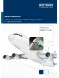
9 50m 10m 3m 10m 10m 10m 10m 10m Figure 2. ISO 10844 specifies test tracks for vehicle Noise emissions tests. You can use these same standards for Noise source location Using Acoustic Beamforming to reduce echoing and ensure repeatability between tests. Measurements Resolution and Dynamic Range Two of the most important aspects of any sound measurement, including Beamforming , are the resolution and dynamic range of the measurement. Both of these aspects are dependent on the hardware in the system making the sound measurements, including the microphone array and the data acquisition hardware.
10 Throughout this paper, explore recommendations on how to choose appropriate system components to maximize resolution and dynamic range. [ back to page one ] | 3. Resolution in sound localization is more specifically spatial resolution, and refers to the ability of the system to resolve two separate sound sources from each other. The higher the spatial resolution, the closer the sound sources can be to each other and still register as two separate sound sources. The resolution of the system is dependent on the distance the sensors are from the source and the size of the microphone array.