Transcription of Using FIELDVUE Instruments with the Smart Loop Interface ...
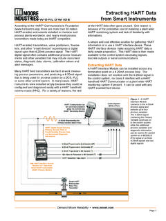
1 Instruction Manual Supplement FIELDVUE Instruments D103263X012. June 2009. Supplement to HARTR Communicating FisherR. FIELDVUER Instrument Instruction Manuals Using FIELDVUER Instruments with the Smart HARTR Loop Interface and Monitor (HIM). Fisher FIELDVUE Instruments can be used in conjunction with a hart Interface module, such as the Smart hart Loop Interface and Monitor (HIM). from Moore Industries, to provide additional diagnostic coverage. Installed transparently across the 4-20 mA instrument loop, the HIM receives the hart digital process data and converts the digital information into up to three scalable, isolated analog (4-20 mA) process signals and two relay outputs that are readily accepted by an existing control system, such as a DCS or PLC. For additional information on the HIM, refer to HIM Smart hart Loop Interface and Monitor Instruction Manual, 224-778-00, or the Moore Industries web site, at The relay outputs are configurable within the HIM.
2 And can be used to indicate instrument status and detailed alert information. For example, when a DVC6000 SIS Series digital valve controller in a Safety Instrumented System (SIS) application Figure 1. Moore Industries hart Loop Monitor instructs the safety valve to move during the partial stroke test, the hart Interface module receives the digital signal representing valve position. The HIM Additionally, the discrete relay output could also be reads this signal, and, depending on the Fail Safe used for various other alerts generated by the mode, energizes a relay at a configured trip point DVC6000 SIS, such as Diagnostics in Progress, (such as 90%). The relay output is sent to the control Valve Stuck Alert etc. system verifying the desired position has been achieved. The HIM operates from an external 24 volts DC . When the digital valve controller instructs the valve 10% voltage source and connects to the 4-20 mA.
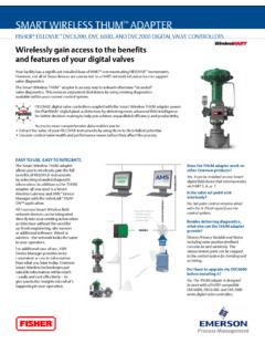
3 To return to the open position, the HIM energizes a control signal lines. second relay when the valve is fully open. This allows the control system to verify and report that the valve is fully reopened and the test is complete. The HIM requests information from the FIELDVUE . Depending on how the HIM is wired to the control instrument. The FIELDVUE instrument responds by system, the relay outputs may be normally open sending the appropriate data. Figure 2 shows a (NO) or normally closed (NC) contacts. In this typical installation of a FIELDVUE instrument with example, the relay outputs are configurable in the the HIM. The HIM is not recommended for HIM, and do not reflect the status byte configuration FIELDVUE instrument applications involving split in the FIELDVUE instrument. ranging. Instruction Manual Supplement FIELDVUE Instruments June 2009. FIELDVUE DVC6000 SIS.
4 Digital Valve Controller 4-20 mA Valve Control Signal with Superimposed hart Digital Signal hart . Digital Communication Relay #1. Valve 90% Open Relay #2. Valve Full Open Control 4 20 mA System Valve Travel 4 20 mA. Output Pressure Smart hart Loop Interface and Monitor Figure 2. FIELDVUE DVC6000 SIS Series Digital Valve Controller Installed with a Moore Industries hart Loop Monitor 130mm ( in). 118mm ( in). Figure 3. HIM hart Loop Monitor Dimensions 2. Instruction Manual Supplement June 2009 FIELDVUE Instruments HAZARDOUS AREA NON-HAZARDOUS AREA. FISHER HF300 SERIES hart . FILTER OR LC340 LINE CONDITIONER. + + + +. ANALOG OUTPUT TO. FLD COMM SYS FIELDVUE INSTRUMENT.. CONTROLLER ANALOG. INPUT CHANNEL. INTRINSIC. SAFETY BARRIER 4 20 mA ANALOG. IF REQUIRED BY + hart OUTPUT CONTROLLER DISCRETE. APPLICATION INPUT CHANNEL. CONTROL ROOM. +INB. INB. +OUT. OUT. FIELDVUE .
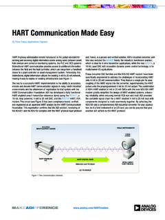
5 DIGITAL VALVE hart LOOP Interface PERC. CONTROLLER AND MONITOR (HIM). DISCRETE. OUTPUT. 24 VDC POWER. NOTE: REFER TO Smart hart LOOP Interface AND MONITOR USERS' MANUAL. 224-778-00 AVAILABLE FROM MOORE INDUSTRIES FOR MORE DETAILED. WIRING INFORMATION. Figure 4. Example HIM Smart hart Loop Interface and Monitor Installation with a FIELDVUE Digital Valve Controller Installation Considerations HIM does not add a requirement for a filter. Refer to the appropriate FIELDVUE instrument instruction The HIM design allows two different DIN-rail manual for detailed installation instructions. For mounting options: instructions on installing the hart filter, refer to the HF300 Series instruction manual . For instructions 32mm (EN50035) G rail on installing the LC340 line conditioner, refer to the LC340 Line Conditioner instruction manual. 35mm (EN50022) top hat rail In addition to performing the designed function, the The HIM dimensions are shown in figure 3.
6 Filter or line conditioner also provides a convenient method for connecting field wiring between the Figure 4 shows the proper installation of a control system, the signal converter, and the FIELDVUE digital valve controller with the HIM. The FIELDVUE instrument. If no filter or conditioner is schematic depicts a Fisher HF340 hart filter in the required, the HF341 communication tap is available. loop when the digital valve controller is operating This device provides the connection convenience with a 4-20 mA control signal. If the digital valve but without filter action (straight-through). When a controller is operating from a 24 volt DC source, a DLC3010 digital level controller is used with the HIM, Fisher LC340 line conditioner is substituted for the a hart filter or line conditioner is not required (see hart filter. The necessity of a hart filter for 4-20 figure 5).
7 However, the HF341 communication tap mA operation depends upon the control system; the may be used for connection convenience. 3. Instruction Manual Supplement FIELDVUE Instruments June 2009. HAZARDOUS AREA NON-HAZARDOUS AREA. ANALOG INPUT CHANNEL FOR. PRIMARY VARIABLE (PV) FROM. FIELDVUE INSTRUMENT). +. SENSE RESISTOR . ANALOG (230 TO 1100 OHMS). + OUTPUT. INTRINSIC. SAFETY BARRIER 4 20 mA CONTROLLER ANALOG. IF REQUIRED BY + hart + IN IN INPUT CHANNEL. FIELDVUE +. APPLICATION. DIGITAL LEVEL. CONTROLLER CONTROLLER DISCRETE. INPUT CHANNEL. +INB. INB. +OUT. OUT. hart LOOP Interface IN CONTROL ROOM. AND MONITOR (HIM). DISCRETE. OUTPUT. 24 VDC POWER. NOTE: REFER TO Smart hart LOOP Interface AND MONITOR USERS' MANUAL. 224-778-00 AVAILABLE FROM MOORE INDUSTRIES FOR MORE DETAILED. WIRING INFORMATION. IN ORDER TO MEET THE hart LOOP IMPEDANCE REQUIREMENT, THERE. MUST BE BETWEEN 230 AND 1100 OHMS IN SERIES WITH THE VOLTAGE.
8 SOURCE. Figure 5. Example HIM Smart hart Loop Interface and Monitor Installation with a FIELDVUE Digital Level Controller HIM Configuration HIM Displayed Data This shows what appears on the display at the front of the HIM. This information is The HIM Operating Parameters can be configured programmed on the Display page. Using HIM PC Configuration Software. The software is composed of the following sections as shown in figure 6. Progress This bar stays in motion any time the HIM. is monitoring, uploading or downloading. 1. HIM Status and Information Section The left side of the screen includes seven boxes that display the different settings of the attached HIM. Communication Status Monitors the PC software's ability to communicate with the HIM. Program Status Displays the activity of the connected HIM. It indicates if the unit is Idle, Uploading, Downloading, Monitoring or Searching.
9 2. hart /Display/Alarms/Analog Outputs/. Custom Curve/Scaling Tabs Clicking these tabs HIM Device Info Displays the individual brings up the corresponding page on the right side of characteristics of the attached HIM, such as its the screen. Each page permits setting up the identity, hardware and software revisions, and the appropriate part of the HIM's configuration. Refer to last date that the device was configured. the HIM users manual for more details. For recommended application guidelines see table 1. HIM Tag A phrase used to identify the HIM. HIM Device Status Displays functioning of the HIM. After making the necessary configuration changes OK is displayed if it is operating normally, otherwise on each page, click the Quick Set button to send an error message is displayed. entered values to the HIM. 4. Instruction Manual Supplement June 2009 FIELDVUE Instruments Figure 6.
10 The hart Menu Sets the hart Communications Parameters Using the HIM PC Configuration Software Table 1. HIM Application Guidelines Page HIM Output Parameter DVC5000 DVC6000 / DVC2000 DVC6000 SIS DLC3010. Mode Normal Burst Normal Burst Normal Normal Burst hart Master Mode Primary Primary Primary Primary . hart Address 0 0 0 0 . Display Source FV PV FV FV FV PV PV. Display Custom Label PERC PERC PERC PERC PERC. User's Trip Alarm Field Device Fault Field Device Fault Field Device Fault Field Device Fault Choice, Low User's User's Alarm 1 Alarm Device Alarm Device Alarm Device Alarm Device See tables FV Choice Choice Malfunction Malfunction Malfunction Malfunction 5 and 6 91%. User's Trip Alarm Alarm Field Device Fault Field Device Fault Field Device Fault Field Device Fault Choice, High User's User's Alarm 2 Alarm More Alarm More Alarm More Alarm More See tables FV Choice Choice Status Available(2) Status Available(2) Status Available(2) Status Available(2).