Transcription of Verilog - Modules - College of Engineering
1 Verilog - Modules The module is the basic unit of hierarchy in Verilog I Modules describe: I boundaries [ module , endmodule]. I inputs and outputs [ports]. I how it works [behavioral or RTL code]. I Can be a single element or collection of lower level Modules I module can describe a hierarchical design (a module of Modules ). I A module should be contained within one file I module name should match the file name I module fadder resides in file named I Multiple Modules can reside within one file (not recommended). I Correct partitioning a design into Modules is critical Verilog - Modules (cont.). A sample module //-------------------------------------- ----------------- //one-bit full adder module //-------------------------------------- ----------------- module fadder(.)
2 Input a, //data in a input b, //data in b input cin, //carry in output sum_out, //sum output output c_out //carry output );. wire c1, c2, c3; //wiring needed assign sum_out = a ^ b ^ cin; //half adder (XOR gate). assign c1 = a //carry condition 1. assign c2 = b //carry condition 1. assign c3 = a //carry condition 1. assign c_out = (c1 + c2 + c3);. endmodule What kind of logic do you expect synthesis to produce? This is always a good question to ask. Verilog - Modules (cont.). When is synthesized by dc shell, we Verilog - Modules (cont.). Two brief and assign I wire . I The declaration wire simply is what you think it is I A wire carries a value. It has no memory or sense of state. I More later about I assign . I The assign statements may execute in any order I We can consider that they are executed simultaneously I This is how the logic would operate Verilog - Modules (cont.
3 Modules are declared with their name and ports Listing 1: Spice file for KVL problem %\ scriptsize % sets right font size for the code %\ begin { verbatim }. module fadder (. input a , // data in a input b , // data in b input cin , // carry in output sum \ _out , // sum output output c \ _out // carry output );. %\ end { verbatim }. Verilog - Modules (cont.). Some Lexical Conventions - Comments I Comments are signified the same as C. I One line comments begin with // . I Multi-line comments start: /*, end: */. Some Lexical Conventions - Identifiers I Identifiers are names given to objects so that they may be referenced I They start with alphabetic chars or underscore I They cannot start with a number or dollar sign I All identifiers are case sensitive Verilog - Modules (cont.)
4 ANSI C Style Ports are declared as I input //simple input I output //simple output I inout //tri-state inout Input port I Always understood as a net within the module I Can only be read from [check this against SVerilog]. Output port I Understood as a net by default I Can be type logic as well Inout port I Understood as a net by default I Is always a net Verilog - Modules (cont.). Testbench Modules I To test a chip at the top hierarchical level, we use a testbench I Testbench encompasses the chip at the top level I Testbench has no ports,..but probably some file i/o Verilog - Modules (cont.). module to module Connections I A hierarchical design has a top level module and lower level ones I Lower level Modules are instantiated within the higher level module I Lower level Modules are connected together with wires Verilog - Modules (cont.)
5 Lower level Modules can be instantiated within the upper one: //-------------------------------------- ----------------------------- //one bit full adder - using builtin Verilog gates //-------------------------------------- ----------------------------- module fadder_struct(. input a, //data in a input b, //data in b input cin, //carry in output sum_out, //sum output output c_out //carry output );. wire c1, c2, c3, psum; //wiring needed xor xor_0 (a, b, psum); //half-adder partial output xor xor_1 (psum, cin, sum_out); //half-adder output and and_0 (a, cin, c1); //carry condition 1. and and_1 (b, cin, c2); //carry condition 2. and and_2 (a, b, c3); //carry condition 3. or or_0 (c1, c2, c3, c_out); //form carry output endmodule Verilog - Modules (cont.)
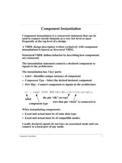
6 Back to Typically, complex Modules are connected under the top level // module instantiations shift_reg shift_reg_1(..clk (clk_50), .reset_n (reset_n), .data_ena (data_ena), .serial_data (serial_data), .parallel_data (shift_reg_out));. ctrl_50mhz ctrl_50mhz_0(..clk_50 (clk_50), .reset_n (reset_n), .data_ena (data_ena), .a5_or_c3 (a5_or_c3), .wr_fifo (wr_fifo));. %[draw partial block diagram showing connections]. Verilog - Modules (cont.). Dissection of shift reg instantiation shift_reg shift_reg_1( // module name and instance of the module .clk (clk_50), //the pin clk is connected to the wire clk_50..reset_n (reset_n), //the "." denotes the pin .data_ena (data_ena), //the value in the parens is the wire .serial_data (serial_data), .parallel_data (shift_reg_out)); //wires and pins do not have to match [show with arrows and such the various parts].
7 This method of declaring pins/wires is called named association . This is the preferred way of doing instantiation when pins/names differ. Comment each wire connection if its function is not obvious. Verilog - Modules (cont.). Its possible to connect wires to pins by position alone Called positional association .. just say no! shift_reg shift_reg_1(clk_50,reset_n,data_ena,seri al_data,shift_reg_out);. How do you know its connected correctly? What if the module had 50 pins on it? What if you wanted to add wire in the middle of the list? Do not use Positional Association! It saves time once, and costs you dearly afterwords Verilog - Modules (cont.). System Verilog instantiation short cuts These are useful when most all pins/wires have the same name shift_reg shift_reg_1(.)
8 Clk (clk ), .reset_n (reset_n ), .data_ena (data_ena ), .serial_data (serial_data ), .parallel_data (shift_reg_out));. Implicit naming can shorten this to: shift_reg shift_reg_1(..clk, //implicit .name port connection .reset_n, //implicit .name port connection .data_ena, //implicit .name port connection .serial_data, //implicit .name port connection .parallel_data (shift_reg_out)); //named association, pin/wire differ implicit name and named association form can be mixed as required Verilog - Modules (cont.). Another instantiation short cut ctrl_50mhz ctrl_50mhz_0(..clk_50 (clk_50 ), .reset_n (reset_n ), .data_ena (data_ena), .a5_or_c3 (a5_or_c3), .wr_fifo (wr_fifo));. All pins and wires have the same name, ctrl_50mhz ctrl_50mhz_0(.*); //wow, that's a short cut!
9 This is the most powerful form of implicit association. Its best reserved for use at the top level testbench/top module . Otherwise, it could hide intent. Verilog - Modules (cont.). Unconnected port pins may be left unconnected like ctrl_50mhz ctrl_50mhz_0(..clk_50 (clk_50 ), .reset_n (reset_n ), .data_ena (data_ena), .a5_or_c3 ( ), //parenthesis left empty .wr_fifo (wr_fifo));. Unused ports may be left out of the port recommended Make your intent clear! Verilog - Modules (cont.). Parametrization of Modules allows for module reuse (powerful!). //-------------------------------------- ----------------------------- //Shift register with width parameter //-------------------------------------- ----------------------------- module shift_reg #(parameter width=8) (.)
10 Input reset_n, //reset async active low input clk, //input clock input data_ena, //serial data enable input serial_data, //serial data input output logic [width-1:0] parallel_data //parallel data out );. always @ (posedge clk, negedge reset_n). if(!reset_n) parallel_data <= '0; //could not do "width'd0". else if (data_ena). parallel_data <= {serial_data, parallel_data[width-1:1]};. endmodule In the module declaration, the keyword parameter is not required It does read more clearly however Verilog - Modules (cont.). Paramaterized shift reg could now be instantiated like this: module top_module;. logic [31:0] parallel_data;. wire reset_n, clk, data_ena, serial_data;. //instantiate shift reg, overriding width to 32 bits shift_reg #(.width(32)) sr_inst0(.





![No.283/54/2018-GRIDSOLAR-Part(2) JR/ 7@hr3jl ad]aufa ...](/cache/preview/e/9/9/f/e/5/f/4/thumb-e99fe5f40795c445f6a2c1028ca812b2.jpg)


