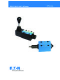
Transcription of Vickers Directional Controls Pilot Operated …
1 Pilot OperatedDirectional Control ValvesDG5S4-10**-53 DG4S4-01-50 Air Gap Pilot ValveDG5S4-10**-80 DG4S4-01-60 Wet Armature Pilot ValveDG5S4 -10** -90DG4V-3S-60 Pilot Valve DG5S4 -10** -100DG4V-3-60 Pilot Valve, High PerformanceNFPA D10, ISO-4401-10669 Released 5/94 Vickers Directional Controls2 Table of ContentsIntroduction3.. Features and BenefitsFunctional SymbolsMinimum Pilot PressureGeneral Information4.. Basic CharacteristicsMounting InterfaceShifting ActionMounting PositionInstallation DataOptional FeaturesService InformationDG5S4-10-53/80 Model Code5.
2 DG5S4-10-53/80 Pressure Drop6.. Flow Ratings7.. DG5S4-10-80 Installation Dimensions8.. DG5S4-10-80 Electrical Information10.. DG5S4-10-53 Air Gap Pilot Options15.. DG5S4-10-90/100 Model Code16.. DG5S4-10-90/100 Installation Dimensions18.. DG5S4-10-90/100 Electrical Informations19.. DG5S4-10-90/100 Optional Features22.. Subplate23.. Application Data24.. 3 IntroductionGeneral DescriptionThese valves are generally used tocontrol the direction of flow in ahydraulic circuit. This, in turn, wouldcontrol the direction of movement of ahydraulic cylinder, or the rotation of afluid motor.
3 DG5S4-10**- 90 uses a DG4V-3S-60standard D03 Pilot valve 100 bar(1450 psi). DG5S4-10**- 100 uses a DG4V-3-60high performance D03 Pilot valve 207 bar (3000 psi). DG5S4-10**- 53 uses a DG5S4-01-50air gap Pilot valve. DG5S4-10**- 80 uses a DG5S4-01-60wet armature Pilot valve 69 bar (1000 psi). XDG5S4-10**-5* Hazardous and Benefits Suitable for the most demandingindustrial applications with flowcapacities up to 946 l/min (250 USgpm) and rated pressure of 207 bar (3000 psi). Available with a wide variety of spooland spring arrangements, stroke andpilot choke adjustments, integral checkvalves, and port orifices.
4 Solid cast body and core passages formaximum strength and minimalpressure drop. Designed and backed by Vickers , withover 70 years as the global leader influid power and motion SymbolsDouble Solenoid - Spring centered,all spoolsABPT abdrain Double Solenoid - No-spring, 0, 2, 6, 9 spoolsABPT abdrain Double Solenoid - Pressure centered,all spoolsABPT abdrain PRPRS ingle Solenoid - Shift to center,all spoolsABPT bdrain Single Solenoid - Spring offset, 0, 2, 6, 9 spoolsABPT bdrain Single Solenoid - Spring centered, all spoolsABPT bdrain Minimum Pilot PressureShifting P to A bar (psi)Shifting P to B bar (psi)
5 Spool TypeFlow l/min(USgpm)Pressure CenteredModels All Other ModelsPressure CenteredModels All Other ModelsAll Spools05,2 (75)5,2 (75)13,8 (200)5,2 (75)0, 4, 8 & 9946 (250)5,2 (75)5,2 (75)13,8 (200)5,2 (75)2, 3, 6 & 33946 (250)10,3 (150)10,3 (150)27,6 (400)10,3 (150) On pressure centered models end covers cannot be interchanged. Pilot pressure is not available through use of integral check InformationDG5S4-10**-** Pilot Operated Directional ValvesBasic CharacteristicsMax. pressure:207 bar (3000 psi)Max. flow:946 l/min (250 USgpm)Max.
6 Pressure port T (external drain):207 bar (3000 psi).. Max. pressure port T (internal drain):DG5S4-10**-53 69 bar (1000 psi)DG5S4-10**-80 69 bar (1000 psi)DG5S4-10**-90 100 bar (1450 psi)DG5S4-10**-100 207 bar (3000 psi)Max. Pilot pressure:207 bar (3000 psi).. Weights: - See installation drawings. Click here for Fluid InterfaceISO 4401-10 NFPA D10 Shifting ActionSpring centered, pressure centered andspring offset models must be energizedcontinuously to maintain the shiftedposition. Detented no-spring modelsmay be energized momentarily(approximately second).
7 Pressure centered and spring centeredmodels return valve spool to centerposition when solenoids are offset models return spool tooffset position by Pilot pressure whensolenoid is no-spring detented models arede-energized, the Pilot and main spoolsremain in the last position attained,provided there is no shock, vibration,unusual pressure transients and thespool axis is horizontal. If Pilot pressurefails or falls below the minimum, themain spool will spring center (at springcentered flow rates) and cannot drift toreversal of flow ( Pilot stage remains indetented position).
8 CautionBecause of this, flow conditions ofthe spring centered position must beselected with care, both for the effecton the direction of the flow, and thepilot pressure. (The 9 main spoolwill not ensure sufficient pilotpressure in the center position.)Pressure centered models: Valvespool is returned to center positionby Pilot pressure, when solenoidsare de-energized. If Pilot pressurefails or falls below the requiredminimum, the valve spool will springreturn to center position. (At springcentered valve flow rates.)CautionSurges of oil in a common tank lineserving these and other valves canbe of sufficient magnitude to causeinadvertent shifting of these is particularly critical in theno-spring detented type tank lines or a ventedmanifold with a continuousdownward path to tank is sliding spool valve, if held forlong periods of time, may stick andnot spring return due to fluid residueformation and therefore, should becycled periodically to prevent thisfrom used as other than a normal4-way valve.
9 Consult your PositionNo-spring detented valves must beinstalled with the longitudinal axishorizontal for good machine mounting position of spring-offsetmodels is unrestricted provided that thepilot pressure supply is maintained asrequired. (Spring offset valves do nothave a spring in the main spool section.)Installation DataPilot Valve DrainInternal: To provide maximum flowwithout malfunction, Pilot pressure ofinternally drained valves must alwaysexceed tank line back pressure by aminimum of 5,2 bar (75 psi) for spooltypes 0, 4, 8 & 9 and a minimum of 10,3bar (150 psi) for all other drain may be used with allvalves, however, an integral pressureport check valve (see optional checkvalve note) is required for valves usingan internal Pilot source with an opencenter spool (0, 4, 8 and 9 types) inorder to maintain Pilot pressure.
10 If anexternal Pilot source is used then anintegral check is not required. Wheninternal Pilot drain is required, orderaccording to model code. (Pressurecentered valves not included.)External: When the possibility ofpressure surges in the tank line exists,externally drained valves arerecommended. For externally drainedmodels, the Pilot valve drain line mustbe piped directly to tank through asurge-free line so there will be no backpressure at this drain. (Referenceconnection Y .)Pressure Centered Drain (external only)External Pilot drain explanation aboveapplies to Y drain port.