Transcription of Vickers Piston Pumps Fixed & variable displacement high …
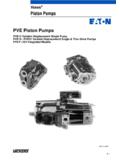
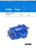
1 & variable displacement high pressure Piston pumps350 bar (5000 psi)PF, PV 20 Design, Open Loop Pumps066 cm3/r ( in3/r) to 250 cm3/r ( in3/r) Vickers Piston Pumps2 ContentsIntroduction3.. General Description3.. Features and Benefits3.. Performance3.. Application3.. Pump Model Codes4.. Control Model Codes6.. Specifications7.. General7.. Hydraulic characteristics7.. Drive7.. Functional Symbol & Control Schematics8.. Performance Characteristics8.. Shaft Input Power8.. Operating Data14.. Theoretical Bearing Life14.. Performance characteristics of variable displacement pumps15.. LR controls; characteristics and calculations16.. Performance Calculations16.. Typical drain flow from an open-loop pump17.. Installation DimensionsPF 066 18.. PF 09019.. PF 130 18020.. PF 25021.. PV 066 250 Rear Ports22.. PV 066 250 Side Ports26.
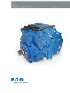
2 Thru-Drive Mounting Dimensions42.. SAE 4-Bolt Mounting Pads43.. Thru-drive Shaft Output Torque43.. Installation data43.. Application DataCase flushing requirements44.. Flushing flow44.. Special fluids44.. Fluid Cleanliness44.. Ordering Procedure44.. Vickers , Incorporated 1999 All Rights Reserved3 Introduction General DescriptionThese Pumps are based on low-noiseswashplate design, with a maximumyoke angle of 18 and can be applied tohydrostatic pistons hydrostatically balanced byshoes bearing on the swashplateprovide virtually pulsation free wide range of control options isavailable for variable displacementpumps, including mechanically,hydraulically and electrically controlledarrangements. These provide highlyefficient system options facilitate themounting of controls, boost or otherauxiliary Pumps . In addition, thethru-drive is of such robust design that asecond pump unit of the same size canbe mounted, thus providing a genuinetandem pump and Benefits A range of control options allowmatching of Pumps to any application.
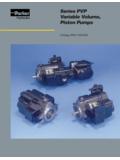
3 high efficiency from automaticpressure balancing of cylinder blockto valve plate. Generously sized shaft bearings forlong life and thru drive capability. Highly resistant to dirt because ofautomatic wear compensation. Low sound level assured byswashplate design and other provenfeatures. Open loop Pumps require noboosting, as they are self pressure350 bar (5000 psi)Maximum geometric displacement66/90/130/180/250 cm3/r( in3/r)Maximum speed1800 r/minApplicationPFFixed single pumpPVVariable single pumpThis catalog contains open loop section, pressure compensated pumpBias springControl pistonControlShaftPistonCylinderblockVal veplateSwashplate4 Model CodesPF Fixed displacementPV variable displacement123456789101 Type2 Displacement066 66,0 cm3/r ( in3/r)090 90,0 cm3/r ( in3/r)130 130,0 cm3/r ( in3/r)180 180,0 cm3/r ( in3/r)250 250,0 cm3/r ( in3/r)3 BuildM ISO Metric4 Direction of rotationR Clockwise (std)L Counterclockwise(not available on PV250)56 Thru driveN No thru drive (std)A SAE A with standard coupling(066,090,130,180,250)B SAE B with standard coupling(066,090,130,180,250)
4 C SAE C with standard coupling(130,180,250)D ISO3019/2-100A2 HWwith standard coupling(066,090,130,180,250)E ISO3019/2-125A2 HWwith standard coupling(066,090,130,180,250)P Pilot pump 8cc/r(066,090,130,180,250)9 Main Port Options1 SAE ports, Metric bolt holesControls11121314151617 SealsBlank NitrileF3 VitonMounting Flange2 ISO3019/2-125A2HW3 ISO3019/2-160A2HW4 ISO3019/2-200A2HW066,090130,180250 displacement Adjustment Stop1 Maximum displacement stop2 No displacement (std)3 Minimum displacement stop4 Maximum & minimum displacement stop7810A Axial rear port (PV models only)R Radial side portMain Port Locatioon111 ISO straight key (std)2 ISO splineDrive Shaft End Type12N No shaft sealS Single shaft seal (std)D Double shaft sealDrive Shaft Seal161710 Control Surfaces nickle plated for SkydrolEU17 Surfaces unpaintedEU19 Grey primer finishEU20 Paint to customer Assemble to another unitSpecial Suffix18 Refer to pages 5 6for control Position IndicatorN No position indicator (std)
5 V Visual position indicatorP Position potentiometerM Potentiometer with visual indicator1520 Pump Design131 Single side of center A 2 Single side of center B 3 Over centerYoke Displacement14PV models onlyPV models onlyPV models onlyPV models onlyPV models onlyControlDescriptionPV Displacementsp066090130180250 DFPressure Compensated & Maximum Flow Adjuster DPProportional to Pilot pressure DQPressure Compensator Over center ESDisplacement Control by Electric Motor LRConstant Power Control FEDisplacement Control by Adjustment Control HGDisplacement Control by Handwheel Adjuster SMDisplacement Control by Servo Valve SPDisplacement Control by Electro Hydraulic Proportional Valve 5 Model CodesDF ControlPressure Compensator & Maximum Flow Adjuster1 Direct operated (std)2 Pilot operatedMaximum Flow AdjustmentF Screw adjuster (std)H HandwheelCompensator pressure Setting090 Std setting 90 bar (1300 psi)xxx Customer requested settingCompensator ControlR Remote connection port only (std)F Screw adjuster on compensator(std)K Electro-proportional relief valvePressure Limiting Valve Operator1 No solenoid valve (std)2 Solenoid unloading valveSolenoid Control VoltageN No solenoidA 110 VAC50 HzB 110 VAC50Hz / 120 VAC60 HzC 220 VAC50 HzD 220 VAC50Hz / 240 VAC60 HzG 12 VDCH 24 VDCLoad Sensing1 No load sensing (std)2 Load sensingDF 1 F 090 R 1 N 1 10 Example of DF model.
6 DP Control displacement ControlProportional to pilot pressurePower ControlN No power control1 Mounting interface only (std)2 Pilot relief & remote port3 Pilot relief, remote port & proportional relief (1-S/S)4 Pilot relief, remote port & proportional relief (2-S/S)Power ControlN No power controlPressure Limiter1 Without pressure limiter (std)2 With pressure limiterPressure Limiting Valve OperationA Single side of center (std)B Over centerSolenoid Control VoltageN No solenoidA 110 VAC50 HzB 110 VAC50Hz / 120 VAC60 HzC 220 VAC50 HzD 220 VAC50Hz / 240 VAC60 HzG 12 VDCH 24 VDCDQ ControlPressure Compensator Over CenterA Mounted on controlB Remote connection only (std)Method of Operation1 Direct operated (std)2 Pilot operatedSolenoid Unloading ValveN No solenoid unloading valve (std)V Solenoid unloading valveCompensator pressure Setting090 Std setting 90 bar (1300 psi)xxx Customer requested settingSolenoid Control VoltageN No solenoidA 110 VAC50 HzB 110 VAC50Hz / 120 VAC60 HzC 220 VAC50 HzD 220 VAC50Hz / 240 VAC60 HzG 12 VDCH 24 VDCDP 1 N 1 A N 10 Example of DP model.
7 DQ B 1 N 090 N 10 Example of DQ CodesES ControlDisplacement Control byElectric MotorResponse time8 Seconds with 50 HZ motor (std)20 Seconds with 50 HZ motor (std)40 Seconds with 50 HZ motorPosition MonitoringA 4 limit switches (std)B 8 limit switchesP 4 limit switches & PotentiometerP 8 limit switches & PotentiometerMotor Type1 Std motor with brake IP44 (std)2 Std motor with brake IP653 Motor without brake hazardous locationsElectric Motor VoltageE 230 / 400 V, 50 Hz 270 / 460 V 3 Phase (std)U 220 V, 50 Hz 1 PhaseV 220 V, 60 Hz 1 PhaseSM N 1 A V 10 Example of SM model:LR ControlConstant Power Control** Specify kW @ 1500 rpm (011 350) pressure LimiterN No pressure limiter (std)F pressure limiting, screw adjusterK pressure limiting, elec. prop. valveLoad Sensing1 No load sensing (std)2 Load sensingHG ControlDisplacement Control byHandwheel AdjusterFE ControlDisplacement Control byAdjustment ScrewSM Control displacement Control byServo ValvePower controlN No power controlPressure Limiter1 Without pressure limiter (std)2 With pressure limiterPressure Limiter Valve OperationA Single side of centerPilot Oil FilterV Filter with visual indicator (std)E Filter with electrical indicatorE Internal pilot supplyProportional Valve1 Mounting interface only (std)2 With proportional valvePilot Oil FilterN Without filter (std)V Filter with visual dirt indicatorE Filter with electrical dirt indicatorFail Safe Solenoid Valve1 Without fail safe valve (std)2 With fail safe valveConstant Power ValveN No power control (std)
8 A With adjustable power controlPressure Limiter1 Without pressure limiter (std)2 With pressure limiterSolenoid Control VoltageN No solenoidA 110 VAC50 HzB 110 VAC50Hz / 120 VAC60 HzC 220 VAC50 HzD 220 VAC50Hz / 240 VAC60 HzG 12 VDCH 24 VDCSP Control displacement Control byElectro-hydraulicProportional ValveES 8 A 1 E 10 Example of ES model:LR 011 N 1 10 Example of LR model:FE 10 Example of FE model:HG 10 Example of HG model:SP E 1 N 1 N 1 N 10 Example of SP SpecificationsGeneral ModelPF/PV 066PF/PV 090PF/ PV 130PF/PV 180PF/PV 250 DesignSwash plate Axial Piston pumpType of mountingFlange or foot-mounted, tandem version foot-mounting onlyPipe connection SAE flangeBApsi11/2 - 30001 - 60002 - 30001 - 600021/2 - 30001 - 600021/2 - 300011/4 - 600031/2 - 50011/4 - 6000 Direction of rotationClockwise when viewing shaft end of pump.
9 Counterclockwise available on rangenminr/min150nmax1800 Installation positionOptional, see mounting informationAmbient temperature rangeminmax C ( F) 20 (25)+50 (250)Weightm3)kg (lbs.)55 (121)75 (165)106 (234)114 (251)212 (467)Hydraulic characteristicsNominal pressure (100% duty cycle)pNbar (psi)350 (5000)Input abs501 abs50 Maximum pressure to DIN 24312p2maxbar (psi)420 (6090)Hydraulic fluidHydraulic oil to DIN 51524 part 2, other fluids on fluid temperaturerangeminmax C ( F) 25 (7) (on startup)+ 90 (380)Viscosity range forcontinuous operationminmaxcSt1075 Max permissible startviscosity maxcSt1000 Filtering18/15/13 Max geom. pumpcapacity3ca acityn=1500 r/minn=1800 r/minVgcm3(in3)66 ( )90 ( )130 ( )180 ( )250 (15)Max geom. pump flown=1500 r/ minQl/min99 (26)135 (36)195 (52)270 (71)375 (99)n=1500 r/ minn=1800 r/minQgl/min(USgpm)99 (26)118 (32)135 (36)162 (43)195 (52)234 (62)270 (71)324 (86)375 (99)450 (119)Case pressurepv maxbarmax.
10 Bar ( psi) over p1, // pv max = 4 bar absDriveMaximum driving torque(p2 max.,h = 100%)M1Nm( )440 (325)600 (443)868 (640)1202 (887)1685 (1243)Maximum powerconsumption(p2 max. n=1500 rpm, ,h = 100%)P1kW (hp)69 (93)94 (126)136 (182)189 (254)265 (355)8 Functional Symbols Basic PumpsPFFixed displacementsingle pump(shown withthru-drive option)PVOpen-loop variabledisplacement singlepump (shown withthru-drive option)Control options for variable displacement pumpsElectrical controlsType ES electric motor displacement controlMResponse time from 0 to +V maximum displacement +VABL++V0 to + UE (IE) electric command signalSBLAFor applications needing moderately fast SM servo control with feedback++V0 to + UE (IE)electric command signalHysteresis < 1%PSTBLAType SP servo control with feedback (piloted by proportional directional valve)For applications needing very fast response.