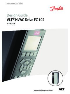
Transcription of VLT 5000 Series
1 ContentsSafety4 Safety regulations5 Warning against unintended start5 Installation of mechanical brake5 Technical data6 General technical data6 Electrical data13 Fuses33 Dimensions41 Mechanical dimensions41 Installation44 Mechanical installation44 Electrical installation - mains supply58 Safety grounding58 Extra protection (RCD)58 RFI switch58 Installation of motor cables62 Connection of motor62 Direction of motor rotation62 Electrical installation - brake cable63 Electrical installation - relay outputs63 Electrical installation - 24 Volt external DC supply63 Electrical installation - load sharing63 Electrical installation - brake resistor temperature switch64 Electrical installation - bus connection64 Installation of control cables65 Connection examples68 Operation of the VLT71 Control panel (LCP)71 Control panel - display71 Control panel - LEDs72 Control panel - control keys72 Quick Setup75 Parameter selection75 Menu mode75 Manual initialization77 Programming79 Operation & Display79 VLT 5000 - VLT is a registered Danfoss trademark.
2 1 Load and motor87 References and limits100 Parameters - Inputs and outputs109 Special functions125 Parameters - Serial communication141 Parameters - Technical functions and diagnostics149 Messages156 Trouble-shooting156 Display - Status messages157 Warnings and alarms160 Warnings161 Examples of use168 Conveyor belt168 Pump169 Gantry Crane170 Torque control, speed feedback171 VLT 5000 controllers172 PID for process control174 PID for speed control175 PID for torque controller (open loop)176EC/EMC177CE labelling177 Electrical Installation181 Electrical installation - EMC precautions181 Electrical installation, selection of EMC-correct cables184 List of functions185 Setting of parameters185 Local and remote control188 Control with brake function189 References - single references190 References - multi-references192 Automatic Motor Adaptation, AMA196 Mechanical brake control198 PID for process control200 PID for speed control201 Quick discharge202 Flying start204 Normal/high overload torque control,open loop206 Programming of Torque limit and stop206 Galvanic Isolation (PELV)
3 207 Extreme Running Conditions209 VLT 5000 Series2 - VLT is a registered Danfoss voltage on motor210 Switching on the input211 Motor thermal protection215 Vibration and Shock215 Air Humidity215 Aggressive environments216 Efficiency217 Interference, Power factor219 Parameters220 Miscellaneous229 Index232 VLT 5000 - VLT is a registered Danfoss trademark. 3 VLT 5000 SeriesInstruction ManualSoftware version: Instruction Manual can be used for all VLT 5000 Series adjustable frequency drives with software software version number can be seen from parameter and C-tick labeling do not cover VLT 5001-5062, 525-600 V VLT Adjustable frequency Drive con-tains dangerous voltages when connec-ted to line voltage. After disconnectingfrom the line wait at least 15 minutes be-fore touching any electrical make sure that other voltage inputshave been disconnected, such as external24 VDC, load-sharing (linkage of DC in-termediate circuit), as well as the motorconnection for kinetic back-up.
4 Only acompetent electrician should carry out theelectrical installation. Improper installa-tion of the motor or the VLT may causeequipment failure, serious injury or this manual and National ElectricalCodes (NEC ) and local safety Precaution; Electrostatic dis-charge (ESD). Many electronic compo-nents are sensitive to static so low that they cannot be felt,seen or heard, can reduce the life, affectperformance, or completely destroy sen-sitive electronic components. When per-forming service, proper ESD equipmentshould be used to prevent possible dam-age from is the responsibility of the user or theperson installing the VLT to provide prop-er grounding, as well as motor overloadand branch circuit protection according tothe National Electrical Code (NEC ) andlocal altitudes above 2000 m, please contactDanfoss Drives regarding 5000 Series4 - VLT is a registered Danfoss frequency converter must be disconnec-ted from mains if repair work is to be carriedout.
5 Check that the mains supply has beendisconnected and that the necessary timehas passed before removing motor andmains [STOP/RESET] key on the control panelof the frequency converter does not discon-nect the equipment from mains and is thusnot to be used as a safety protective earthing of the equipmentmust be established, the user must be pro-tected against supply voltage, and the motormust be protected against overload in ac-cordance with applicable national and earth leakage currents are higher against motor overload is not in-cluded in the factory setting. If this function isdesired, set parameter 128 to data value ETRtrip or data value ETR : The function is initialised at x ratedmotor current and rated motor frequency . Forthe North American market: The ETR func-tions provide class 20 motor overload pro-tection in accordance with not remove the plugs for the motor andmain supply while the frequency converter isconnected to mains.
6 Check that the mainssupply has been disconnected and that thenecessary time has expired before removingmotor and mains note that the frequency converter hasmore voltage inputs than L1, L2 and L3, whenloadsharing (linking of DC intermediate cir-cuit) and external 24 V DC have been instal-led. Check that all voltage inputs have beendisconnected and that the necessary timehas passed before repair work is against unintended motor can be brought to a stop by meansof digital commands, bus commands, refer-ences or a local stop, while the adjustablefrequency drive is connected to the AC stop functions are NOT sufficient toensure that no unintended start occures andshould NOT be used for personal safety parameters are being changed, themotor may start. Consequently, the stop key"Stop/Reset" must always be activated, fol-lowing which data can be motor that has been stopped may start iffaults occur in the electronics of the adjusta-ble frequency drive, or if a temporary over-load or a fault in the AC line supply or themotor connection of mechanical brakeDo not connect a mechanical brake to the output fromthe frequency converter before the relevant parame-ters for brake control are parameterised.
7 (Selection of output in parameter 319, 321, 323 or 326and cut-in current and frequency in parameter 223 and225).Use on isolated AC lineSee section RFI Switch regarding use on isolated is important to follow the recommendations regard-ing installation on IT line, since sufficient protection ofthe complete installation must be observed. Not takingcare using relevant monitoring devices for IT line sup-ply may result in 5000 - VLT is a registered Danfoss trademark. 5 SafetyGeneral technical dataAC line supply (L1, L2, L3):Supply voltage 200-240 V units3 x 200/208/220/230/240 V 10%Supply voltage 380-500 V units3 x 380/400/415/440/460/500 V 10%Supply voltage 525-600 V units3 x 525/550/575/600 V 10%Supply voltage 525-690 V units3 x 525/550/575/600/690 V 10%Supply frequency48-62 Hz +/- 1 %See the section on special conditions in the Design GuideMax.
8 Imbalance of supply voltage:VLT 5001-5011, 380-500 V and 525-600 V and VLT 5001-5006, 200-240 V of rated supply voltageVLT 5016-5062, 380-500 V and 525-600 V and VLT 5008-5027, 200-240 V of rated supply voltageVLT 5072-5500, 380-500 V and VLT 5032-5052, 200-240 V of rated supply voltageVLT 5075-5250, 525-600 V of rated supply voltageTrue Power factor ( ) nominal at rated loadDisplacement Power Factor (cos )near unity (> )No. of switches on supply input L1, L2, L3approx. 1 time/2 shortcircuit rating100,000 AVLT output data (U, V, W):Output voltage0-100% of supply voltageOutput frequency VLT 5001-5027, 200-240 V0-132 Hz, 0-1000 HzOutput frequency VLT 5032-5052, 200-240 V0-132 Hz, 0-450 HzOutput frequency VLT 5001-5052, 380-500 V0-132 Hz, 0-1000 HzOutput frequency VLT 5062-5302, 380-500 V0-132 Hz, 0-450 HzOutput frequency VLT 5352-5552, 380-500 V0-132 Hz, 0-300 HzOutput frequency VLT 5001-5011, 525-600 V0-132 Hz, 0-700 HzOutput frequency VLT 5016-5052, 525-600 V0-132 Hz, 0-1000 HzOutput frequency VLT 5062, 525-600 V0-132 Hz, 0-450 HzOutput frequency VLT 5042-5302, 525-690 V0-132 Hz, 0-200 HzOutput frequency VLT 5352-5602, 525-690 V0-132 Hz, 0-150 HzRated motor voltage, 200-240 V units200/208/220/230/240 VRated motor voltage, 380-500 V units380/400/415/440/460/480/500 VRated motor voltage, 525-600 V units525/550/575 VRated motor voltage.
9 525-690 V units525/550/575/690 VRated motor frequency50/60 HzSwitching on outputUnlimitedRamp characteristics:Starting torque, VLT 5001-5027, 200-240 V and VLT 5001-5552, 380-500 V160% for 1 torque, VLT 5032-5052, 200-240 V150% for 1 torque, VLT 5001-5062, 525-600 V160% for 1 torque, VLT 5042-5602, 525-690 V160% for 1 torque180% for torque100%Overload torque, VLT 5001-5027, 200-240 V and VLT 5001-5552, 380-500 V,VLT 5001-5062, 525-600 V, and VLT 5042-5602, 525-690 V160%VLT 5000 Series6 - VLT is a registered Danfoss torque, VLT 5032-5052, 200-240 V150%Arresting torque at 0 rpm (closed loop)100%The torque characteristics given are for the adjustable frequency drive at the high overload torque level (160%). Atthe normal overload torque (110%), the values are at high overload torque level Cycle time (s)Braking duty cycle at 100% torqueBraking duty cycle at over torque(150/160%)200-240 V 5001-5027120 Continuous40%5032-505230010%10%380-500 V 5001-5102120 Continuous40%5122-5252600 Continuous10%530260040%10%5352-555260040 %1)10%2)525-600 V 5001-5062120 Continuous40%525-690 V 5042-535260040%10%5402-560260040%3)10%4) 1) VLT 5502 at 90% torque.
10 At 100% torque the braking duty cycle is 13%. At mains rating 441-500 V 100% torque the braking dutycycle is 17%.VLT 5552 at 80% torque. At 100% torque the braking duty cycle is 8%.2) Based on 300 second cycle:For VLT 5502 the torque is 145%.For VLT 5552 the torque is 130%.3) VLT 5502 at 80% 5602 at 71% ) Based on 300 second VLT 5502 the torque is 128%.For VLT 5602 the torque is 114%.Control card, digital inputs:Number of programmable digital inputs8 Terminal , 17, 18, 19, 27, 29, 32, 33 Voltage level0-24 V DC (PNP positive logics)Voltage level, logical '0'< 5 V DCVoltage level, logical '1'>10 V DCMaximum voltage on input28 V DCInput resistance, Ri2 k Scanning time per input3 galvanic isolation: All digital inputs are galvanically isolated from the supply voltage (PELV). In addition, thedigital inputs can be isolated from the other terminals on the control card by connecting an external 24 V DC supplyand opening switch 4.