Transcription of Wireless Battery Charging-PBattezzato - st.com
1 Wireless Battery ChargingPaolo Battezzato Applications Engineer Wireless Power Keeps Growing2By 2018over a billion receiver units are expected to be shipped worldwide** Source: IHS October 2016 WearableMobile phones and tabletsPower toolsMedicalSmart homeAutoLeave cables at home and top up batteriesMagnetic induction PRU Category 1-7. PTU Class 1-6 PRXOut Max from to 50W (Cat. 1 TBD) PTXI nput Max from 2W to 70W Wireless Power at a Glance3 Advantagessimple, efficient, safe, power scalable, matureKey technology challenges shield, coil alignment, good coupling Disadvantageslimited x/y/z space, difficult for multiple device operation simultaneouslyMagnetic resonanceAdvantagesspatial freedom, multiple devices support, larger charging areaKey technology challenges power scalable, environment safety, TX and RX designDisadvantagesincreased EMI.
2 EfficiencyDifferent StandardsSimilar technologyDifferent Implementation Low Power: 5W (rel ) Medium Power: 15W (rel ) Qi Cordless kitchen appliances from 100W to Resonant (Under Definition)*Qi by Wireless Power Consortium* PMA by Power Matter AllianceA4WP by Alliance for Wireless PowerNote: A4WP and PMA merged in June 2015is a member of Qi and AirFuel (A4WP + PMA)Organizations Defining Standards4 WPCPMAA4 WPMembers~240~200 under AirFuel Alliance nameAvailable products>950~302 TechnologyInductive and Resonant-LFInductiveResonant-HFInvestmen t areasInfrastructureAutomotivePower increaseLarger ZShared Mode, Resonant ExtensionConsumer awarenessInfrastructureMedium PowerMerge with A4WP (June 15)SpecificationTechnologyIndustrializat ionMarketingCertification program& Test housesMerge with PMA (June 15)
3 ST is Regular Member (*)of WPC and Full Member of AirFuel Alliance (*) also member of the Steering GroupMagnetic Induction Power TransferWPC Qi5 Operating Frequency is 110-205kHz One Base Station typically powers one Mobile Device In-band digital link is used for identification of compatible devices and control of power levels (operates through the same coils used for power transfer)Magnetic Resonance Power Transfer AirFuel6 Operating Frequency is Multiple PRUs can be can be powered from a single PTU A Bluetooth Low Energy (BLE) link is used for identification of compatible devices and control of power levelsIntroduction to WPC Qi Battery charging (Magnetic Induction) Power Transfer Principle Tightly coupled Wireless charging technology uses magnetic induction to transfer power from a transmitter (Tx) to a receiver (Rx).
4 The magnetic field is generated by a coil on the TX side. The field is captured by a coil on the RX side. The field works through air, no magnetic circuit links the coils. The received electrical signal is rectified, filtered and regulated before supplying the Power to Control Magnetic Field To control the field, various solutions can be used (and combined): Use the LC tank properties, changing the oscillator frequency. Change the oscillator duty cycle (using a square wave oscillator) Change the oscillator voltage.
5 Apply phaseshift to a full bridge to TX Communication Because there are too many variables (RX/TX coupling, RX & TX coils, load, ..), the TX cannot set the regulation point by itself. There is then an absolute need of communication from RX to TX: the RX will have to pass data to the TX about the regulation set point. This communication channel can also be used for auxiliary purposes and extended to bi-directional communication10RX Presence Detection and FOD Receiver Presence Detection The transmitter generates a magnetic field at regular intervals and check if a load is present and consumes power.
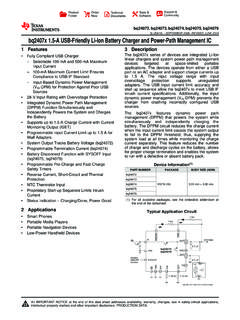
6 FOD (Foreign Object Detection) Qi uses the method of power balance to estimate the presence of foreign object. If the TX transmits more power than what the RX reports, a foreign object is present11Qi Power Transmitter Designs Overview12 Source: WPC Qi specifications, Version Wireless Battery charging Transmitter ICSTWBC - TransmitterFlexible, efficient, compliant with leading standard5V IC supply voltageTwo Firmware options Turn/key solution for quick design APIs available for customizationAPI: Available Peripherals ADC with 10 bit precision and 1M input impedance UART I2C master fast-slow speed rate GPIOs Program memory: 32* kbyte EEPROM (*available size for API depends on selected FW)General application features.
7 Low cost 2-layer PCBs Active object detection Graphical user interface for application monitoring Evaluation board14 STWBC - TransmitterFlexible, efficient, compliant with leading standard15 STWBC TransmitterQi Evaluation BoardsSTWBC - A11 Transmitter Configuration 5W Qi, 1-Coil, 5V supply A11 requires accurate frequency control: Operating frequency range 110kHz 205kHz Duty cycle 50%-10% @ 205kHz17 STWBC 5W A11 Transmitter Reference BoardSTEVAL-ISB027V1 2-Layer PCB and single-side placement18 Ping active 3mWconsumption FOD activeStandBySTWBC A34 Transmitter Configuration Available also as 5W Qi platform for Automotive, 3-Coil system19 Qi protocol, coil choice.
8 Bridge and fly back control handled by the STWBC The transmitter is based on a half bridge topology The inverter bridge is supplied by a Flyback converterST A34 Transmitter Special Recipe20 ST implementation differs from the similar 3-coil A13 design. Here are the differences: Board input voltage: Exactly same (12V) Coil: Exactly same Resonant tank: Similar at 110kHz operating frequency Resonant tank excitation voltage: Exactly same Bridge: Half-bridge instead of full-bridge Bridge supply average power: Exactly same Bridge supply voltage: 2 to 24V instead of 1 to 12V PID: Same except that PID output (scaling factor) is doubled Those modifications have been submitted to Qi consortium under CR305 ID.
9 It has received the A34designation and it is now listed on the Wireless Power Consortium 5W A34 Transmitter Reference BoardSTEVAL-ISB028V1 2-layer PCB and single-side placement (same area as 3-coil assembly)21 Individual LCFront filterFlyback with drive, schottkybarrier diode and capacitorFlyback pre drive and filteringLDO and resetBridge inverter and pre driveCurrent senseCurrent demodulationVoltage demodulationCoil switchGPIO expanderSTWBCF lyback sense filteringDemagnetization circuitryDAC circuitryASTWBC (H1 17): automotive gradeSTWBC-MC.
10 Industrial grade (aftermarket) Ping active 30mWconsumption FOD activeStandBySTWBC Wearable Transmitter Configuration System, bridge control and Qi protocol are handled by the STWBC The transmitter is based on a half bridge topology The inverter bridge is supplied by 5V input voltage22 STWBC 1W Wearable Transmitter Reference BoardSTEVAL-ISB038V1T 2-Layer PCB and single-side placement23LC Power NodePower SupplyHalfBridgeSTWBC digital controllerWavefrequencysensingCurrentsen secircuitSWIM connectorUSB/UART connector20mm CoilTwo System Approaches24 Customize the application around the Wireless Transmitter.