Transcription of WPT 45 SERIES - bigjoesupport.com
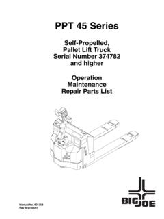
1 WPT 45 SERIES . SELF-PROPELLED, PALLET LIFT TRUCK. Operation Maintenance Repair Parts List Big Lift LLC MANUAL NO. BL-WPT-0118 - 02-27-2018. WARNING. Do not operate this truck unless you have been autho- Always look in direction of travel. Keep a clear view, rized and trained to do so, and have read all warnings and when load interferes with visibility, travel with load and instructions in Operator's Manual and on this trailing. truck. Use special care when operating on ramps travel Do not operate this truck until you have checked its slowly, and do not angle or turn. Travel with load condition. Give special attention to tires, horn, battery, downhill.
2 Controller, lift system, brakes, steering mechanism, Do not handle loads which are higher than the load guards and safety devices. backrest or load backrest extension unless load is Operate truck only from designated operating position. secured so that no part of it could fall backward. Do not carry passengers. Keep feet clear of truck and Before lifting, be sure load is centered, forks are com- wear foot protection. pletely under load, and load is as far back as possible Observe applicable traffic regulations. Yield right of against load backrest. way to pedestrians. Slow down and sound horn at When leaving truck, neutralize travel control, fully cross aisles and wherever vision is obstructed.
3 Lower lifting mechanism and set brake. When leaving truck unattended, also shut off power. Start, stop, travel, steer and brake smoothly. Slow down for turns and on uneven or slippery surfaces that could cause truck to slide or overturn. Use special care when traveling without load as the risk of overturn may be greater. TABLE OF CONTENTS. Section Page Section Page 1 LIST OF ILLUSTRATIONS ..1-II STEERING ARM INSTALLATION.. 5-6. 5-3. COMPARTMENT 5-6. 1 LIST OF REMOVAL.. 5-6. 1 INSTALLATION.. 5-6. 6. 1-1. INTRODUCTION..1-1 BRAKE 6-1. 1-2. GENERAL 6-1. BRAKES.. 6-1. 1-3. SAFETY FEATURES..1-2 AIR GAP ADJUSTMENT.. 6-1. 2 STOPPING DISTANCE ADJUSTMENT.. 6-2.
4 OPERATION ..2-1 BRAKE ASSEMBLY REPLACEMENT .. 6-2. 2-1. GENERAL..2-1 7. 2-2. OPERATING PRECAUTIONS..2-1 TRANSMISSION, DRIVE WHEEL, LOAD 7-1. 2-3. BEFORE 7-1. DRIVE WHEEL.. 7-1. 2-4. GENERAL CONTROL 7-2. TRANSMISSION.. 7-1. 2-5. DRIVING AND STOPPING PROCEDURES..2-4 7-3. LOAD WHEEL.. 7-2. 2-6. BELLY-BUTTON SWITCH..2-4 REMOVAL .. 7-2. 2-7. STEERING ARM GAS REPAIR .. 7-2. 2-8. LIFT AND LOWER CONTROLS..2-5 LOAD WHEEL 7-2. 2-9. LOADING AND UNLOADING..2-5. 2-10. PARKING..2-5 8. ELEVATION SYSTEM 8-1. 3 8-1. 8-1. PLANNED MAINTENANCE ..3-1 8-2. LIFT 8-1. 3-1. GENERAL..3-1 REMOVAL .. 8-1. 3-2. MONTHLY AND QUARTERLY CHECKS..3-1 INSTALLATION .. 8-1. 3-3. BATTERY CARE.
5 3-1 8-3. POWER SECTION AND FORK 8-1. GENERAL ..3-1 SEPARATING POWER SECTION. SAFETY RULES ..3-2 AND FORK SECTION .. 8-1. BATTERY CARE AND CHARGING ..3-2 FORK FRAME REPAIR.. 8-1. BATTERY CARRIER FRAME 8-1. MAINTENANCE FREE MATING POWER SECTION. 3-4. CHARGING BATTERIES ..3-3 AND FORK SECTION .. 8-1. 3-5. LUBRICATION..3-4. 9. 4 HYDRAULIC SYSTEM SERVICING .. 9-1. TROUBLESHOOTING ..4-1 9-1. LINES AND FITTINGS .. 9-1. 4-1. GENERAL ..4-1 9-2. HYDRAULIC PUMP, MOTOR, 4-2. CONTROLLER AND RESERVOIR ASSY .. 9-1. ZAPI HANDSET ..4-4 REMOVAL .. 9-1. FAULT DETECTION..4-4 DISASSEMBLY AND REASSEMBLY .. 9-3. TESTING TRUCK OPERATION..4-4 INSTALLATION .. 9-3. SETTINGS AND ADJUSTMENTS.
6 4-5 LIFT CYLINDER .. 9-3. 5 10. STEER ARM, CONTROL HEAD & COMPARTMENT ..5-1 ELECTRICAL 10-1. 5-1. CONTROL HEAD ..5-1 10-1. ELECTRICAL CONTROL PANEL .. 10-1. CONTROL HEAD REMOVAL ..5-1 10-1. CONTROL HEAD INSTALLATION ..5-2 .. 10-1. CAP ASSEMBLY REMOVAL..5-3 REMOVAL.. 10-1. CAP ASSEMBLY INSTALLATION..5-3 10-1. BELLY-BUTTON SWITCH REPLACEMENT..5-3 INSTALLATION.. 10-1. HORN SWITCH 10-2. HORN REPLACEMENT .. 10-3. LIFT & LOWER SWITCH REPLACEMENT ..5-5 10-3. PUMP MOTOR.. 10-4. SPEED POTENTIOMETER REPLACEMENT .5-6 10-4. DRIVE MOTOR.. 10-4. 5-2. STEERING ARM ..5-6 10-4. RETURN SPRING REPAIR .. 10-4. STEERING ARM 10-4. BL-WPT-0118 - 02-27-2018 i TABLE OF CONTENTS - Continued 10-5.
7 LIFT LIMIT SWITCH .. 10-6 OPTIONAL EQUIPMENT .. 11-1.. 10-6 11-1. LOAD BACKREST.. 11-1. 10-6 11-2. CASTERS .. 11-1. 10-6. DEADMAN 10-6.. 10-6 12. ILLUSTRATED PARTS BREAKDOWN .. 12-1. 11. LIST OF ILLUSTRATIONS. Figure Page Figure Page 1-1 NAME PLATE .. 1-1 10-4 DRIVE MOTOR .. 10-5. 1-2 WPT 45 LIFT TRUCK .. 1-1 12-1 STEERING ARM .. 12-2. 2-1 SAMPLE OF OPERATOR CHECK LIST .. 2-3 12-2 CONTROL HEAD .. 12-4. 2-2 FORWARD/REVERSE 2-4 12-3 CAP 12-6. 2-3 PUSHBUTTON SWITCHES .. 2-4 12-4 EMERGENCY REVERSE SWITCH. 2-4 BRAKE ACTUATION .. 2-4 ASSEMBLY .. 12-8. 2-5 BELLY-BUTTON 2-5 12-5 TRANSMISSION, MOTOR, BRAKE. 3-1 LUBRICATION DIAGRAM .. 3-5 ASSEMBLY .. 12-10. 4-1 CONNECTING THE 4-4 12-6 TRANSMISSION, 4-2 ZAPI HANDSET.
8 4-5 USED FROM SERIAL # 12-12. 4-3 ZAPI HANDSET .. 4-9 12-7 COMPARTMENT .. 12-14. 4-4 THROTTLE 4-10 12-8 CASTER WHEEL (OPTIONAL). 4-5 ZAPI HANDSET .. 4-11 USED UP TO SERIAL # E2210274 .. 12-16. 4-6 ZAPI CONTROLLER CONNECTIONS .. 4-13 12-9 CASTER WHEEL (OPTIONAL). 5-1 STEERING 5-1 USED FROM SERIAL # 12-18. 5-2 CONTROL 5-2 12-10 FRAME .. 12-20. 5-3 EMERGENCY REVERSE SWITCH ASSY .. 5-3 12-11 LINKAGE .. 12-24. 5-4 CAP ASSEMBLY .. 5-4 12-12 LOAD WHEEL .. 12-28. 5-5 LEFT LIFT/LOWER SWITCH ASSY .. 5-5 12-13 HYDRAULIC SYSTEM .. 12-30. 6-1 BRAKE 6-1 12-14 PUMP & MOTOR 12-32. 7-1 TRANSMISSION, MOTOR, BRAKE 7-1 12-15 LIFT CYLINDER .. 12-34. 7-2 WHEEL ASSEMBLY.
9 7-2 12-16 ELECTRICAL 12-36. 8-1 FRAME (SHEET 1) .. 8-2 12-17 ELECTRICAL 12-38. 8-2 FRAME (SHEET 1) .. 8-2 12-18 DRIVE MOTOR .. 12-40. 9-1 HYDRAULIC 9-2 12-19 WIRING 12-42. 9-2 PUMP AND MOTOR ASSEMBLY .. 9-3 12-20 WIRING CABLES .. 12-44. 9-3 LIFT 9-4 12-21 BATTERY ASSY. 10-1 ELECTRICAL SYSTEM .. 10-2 USED FROM SERIAL 12-46. 10-2 ELECTRICAL PANEL .. 10-3 12-22 COLD CONDITIONING .. 12-48. 10-3 TRANSMISSION, MOTOR, BRAKE. 10-4. LIST OF TABLES. Table Page Table Page 2-1 OPERATOR 2-2 4-1 TROUBLESHOOTING 3-1 MONTHLY AND QUARTERLY INSPECTION 4-2 SET OPTIONS ..4-5. AND SERVICE CHART .. 3-1 4-3 3-2 RECOMMENDED LUBRICANTS .. 3-4 4-4 PARAMETER ADJUSTMENTS .. 4-11.
10 3-3 LUBRICATION CHART .. 3-5 4-5 ZAPI CONTROLLER CONNECTOR PINS .. 4-13. ii BL-WPT-0118 - 02-27-2018. SECTION 1. DESCRIPTION. 1-1. INTRODUCTION. forks raised or lowered. The lift truck must be pro- This publication describes the 24 volt transistor tected from the elements. WPT 45 lift truck distributed by Big Lift LLC. Included The model number will be found on the name plate are operating instructions, planned maintenance (Figure 1-1) along with the serial number, lifting capac- instructions, lubrication procedures, corrective mainte- ity, and load center. Figure 1-2 shows the locations of nance procedures and a complete parts list with part the truck's main components and controls.