Class D Amplifier Design Basics II - irf.com
Noise immunity Inherently immune to incoming noise; low drive impedance, inductor between the load and amplifier. Because of strong non-linearity in device and 'exposed' feedback node, weak to RF noise. Reliability Higher reliability from less heat. Less metal fatigue in solder joints. Linearity Stability
Download Class D Amplifier Design Basics II - irf.com

Information
Domain:
Source:
Link to this page:
Documents from same domain
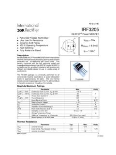
PD-91279E IRF3205 - Infineon Technologies
www.irf.comIRF3205 www.irf.com 3 Fig 1. Typical Output Characteristics Fig 2. Typical Output Characteristics Fig 3. Typical Transfer Characteristics Fig 4.
Application Note AN-1068 revA Considerations for …
www.irf.comApplication Note AN-1068 revA Considerations for Designs Using Radiation-Hardened Solid State Relays By Alan Tasker Table of Contents Introduction Page
IGBT reverse conduction characteristics Hard …
www.irf.comCOMPANY CONFIDENTIAL 18 IGBT reverse conduction characteristics Hard-switching and soft-switching Energy Saving Products BU July 2013
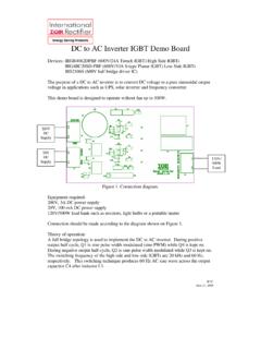
DC to AC Inverter IGBT Demo Board - Infineon …
www.irf.comWTC June 27, 2008 Eneerrggyy Saavviinngg cPPrroodduucttss DC to AC Inverter IGBT Demo Board Devices: IRGB4062DPBF (600V/24A Trench IGBT) High Side IGBTs
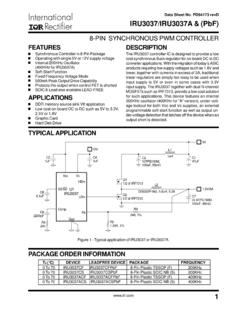
Data Sheet No. PD94173 revD IRU3037/IRU3037A …
www.irf.comIRU3037/IRU3037A & (PbF) www.irf.com 1 TYPICAL APPLICATION DESCRIPTION The IRU3037 controller IC is designed to provide a low cost synchronous Buck regulator for on-board DC to DC
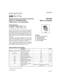
REPETITIVE AVALANCHE AND dv/dt RATED IRF460 …
www.irf.comAbsolute Maximum Ratings Parameter Units ID @ VGS = 10V, TC = 25°C Continuous Drain Current 21 ID @ VGS = 10V, TC = 100°C Continuous Drain Current 14
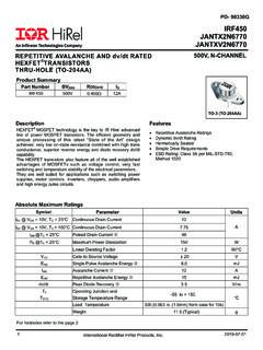
REPETITIVE AVALANCHE AND dv/dt RATED IRF450 …
www.irf.comAbsolute Maximum Ratings Parameter Units ID @ VGS =0V, TC = 25°C Continuous Drain Current 12 ID @ VGS = 0V, TC = 100°C Continuous Drain Current 7.75
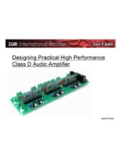
Designing Practical High Performance Class D Audio …
www.irf.comwww.irf.com Contents • Class D Amplifier Introduction • The latest Digital Audio MOSFET, DirectFET® MOSFET • Designing Dead-time and Overload Protection with Digital Audio Gate
HIGH POWER, HIGH CURRENT OPERATIONAL …
www.irf.com3.4 - 41 3.4 8-Pin, TO-3 And DIP, 10 Amp Monolithic Power Operational Amplifier 4 11 R1 Supersedes 2 05 R0 HIGH POWER, HIGH CURRENT OPERATIONAL AMPLIFIER
Irf9z24n - Infineon Technologies
www.irf.comIRF9Z24N Parameter Min. Typ. Max. Units Conditions IS Continuous Source Current MOSFET symbol (Body Diode) ––– ––– showing the ISM Pulsed Source Current …
Related documents
RF Agile Transceiver Data Sheet AD9361 - Analog Devices
www.analog.comThe device combines a RF front end with a flexible mixed-signal baseband section and integrated frequency synthesizers, simplifying design-in by providing a configurable digital interface to a processor. The AD9361 receiver LO operates from 70 MHz to 6.0 GHz and the transmitter LO operates from 47 MHz to 6.0 GHz

RF, Microwave, and Millimeter Wave Products
www.analog.comRF/IF Differential Amplifiers 16 Low Noise Amplifiers 18 ADL9005: Wideband, Low Noise Amplifier, Single Positive Supply, 0.01 GHz to 26.5 GHz 20 ADL9006CHIPS: 2 GHz to 28 GHz, GaAs, pHEMT, MMIC Low Noise Amplifier 20 ADL8104: Wideband, High Linearity, Low Noise Amplifier, 0.4 GHz to 7.5 GHz 21

airFiber AF-5XHD Datasheet - Ubiquiti
dl.ubnt.comprocessing, the innovative RF design delivers ultra-clean power output that improves noise immunity and co-location performance. This reduces the potential impact on the RF noise environment and allows for the use of higher-order modulation, such as 1024QAM. * Available with a future firmware upgrade
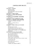
CHAPTER 4 RF/IF CIRCUITS - Analog Devices
www.analog.comBASIC LINEAR DESIGN 4.2 The basic concept of operation is as follows. For the receiver, the signal from the antenna is amplified in the radio frequency (RF) stage. The output of the RF stage is one input of a mixer. A Local Oscillator (LO) is the other input. The output of the mixer is at the Intermediate Frequency (IF).
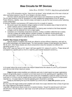
Bias Circuits for RF Amplifiers - QSL.net
www.qsl.netThe bias network determines the amplifier performance over temperature as well as RF drive. The DC bias condition of the RF transistors is usually established independently of the RF design. Power efficiency, stability, noise, thermal runway, and ease to use are the main concerns when selecting a bias configuration.

Project Report A 5.2 GHz Differential Cascode Low Noise ...
images.template.netThe purpose of this project was the design of a Low Noise Amplifier (LNA) at 5.2 GHz for wireless Local Area Network (LAN) applications. The LNA was designed to meet specifications that were set to ensure that the LNA would be able to operate in a complete receiver. The field of Radio Frequency Integrated Circuit (RFIC) design is a growing one as a