
Complementary low voltage transistor
Complementary low voltage transistor Features Products are pre-selected in DC current gain Application General purpose Description These epitaxial planar transistors are mounted in the SOT-32 plastic package. They are designed for audio amplifiers and drivers utilizing complementary or quasi-complementary circuits.
Download Complementary low voltage transistor

Information
Domain:
Source:
Link to this page:
Documents from same domain

Low-power dual operational amplifier - st.com
www.st.comFebruary 2016 DocID2471 Rev 17 1/24 This is information on a product in full production. www.st.com LM2904, LM2904A Low-power dual operational amplifier

AN3128 Application note - st.com
www.st.comJune 2011 Doc ID 16918 Rev 5 1/105 AN3128 Application note STM32 embedded graphic objects/touchscreen library Introduction This library is a firmware package which contains a collection of routines, data structures,

AN4767 Application note - st.com
www.st.comDocID028380 Rev 2 7/16 AN4767 Dual bank use cases 15 With dual bank, all the manipulation with the other bank is just another task of the main program.

AN3155 Application note - st.com
www.st.comOctober 2016 DocID17066 Rev 7 1/37 1 AN3155 Application note USART protocol used in the STM32 bootloader Introduction This application note describes the USART protocol used in the STM32 microcontroller

USB Power Delivery and Type-C - st.com
www.st.comUSB Type -C Overview USB Power Delivery specification introduces USB Type-C receptacle, plug and cable; they provide a smaller, thinner and more robust alternative to existing USB interconnect.

Datasheet - L78 - Positive voltage regulator ICs - …
www.st.comTO- 2 2 0 TO-2 2 0 F P DPAK D² PAK Features • Output current up to 1.5 A • Output voltages of 5; 6; 8; 8.5; 9; 12; 15; 18; 24 V • Thermal overload protection

AN2867 Application note - st.com
www.st.comMay 2017 DocID15287 Rev 11 1/43 1 AN2867 Application note Oscillator design guide for STM8AF/AL/S and STM32 microcontrollers Introduction Many designers know oscillators based on Pierce-Gate topology (hereinafter referred to as

AN4776 Application note - st.com
www.st.comMay 2017 DocID028459 Rev 2 1/73 1 AN4776 Application note General-purpose timer cookbook Introduction The timer peripheral is part of …

120-volt, 100-watt, DMOS audio amplifier with mute …
www.st.comSeptember 2010 Doc ID 6744 Rev 8 1/21 21 TDA7293 120-volt, 100-watt, DMOS audio amplifier with mute and standby Features Multipower BCD technology Very high operating voltage range (±50 V)

Electronic transformer for a 12V halogen lamp - …
www.st.comAPPLICATION NOTE AN528/0999 1/4 ELECTRONIC TRANSFORMER FOR A 12V HALOGEN LAMP by P. Fichera, R. Scollo 1. INTRODUCTION Lighting that uses halogen lamps is commonly found
Related documents
Basic Electronics
engineering.nyu.eduTransistor • A three lead semiconductor device that acts as: – an electrically controlled switch, or – a current amplifier. • Transistor is analogous to a faucet. – Turning faucet’s control knob alters the flow rate of water coming out from the faucet.

CMOS Manufacturing Process
bwrcs.eecs.berkeley.eduDigital Integrated Circuits Manufacturing Process EE141 A Modern CMOS Process p-well n-well p+ p-epi SiO 2 AlCu poly n+ SiO 2 p+ gate-oxide Tungsten TiSi 2 ... Transistor Layout 1 2 5 3 T r a n s i s t o r. Digital Integrated Circuits Manufacturing Process EE141 Vias and Contacts 1 2 1 Via Metal to Metal to Poly Contact Active Contact 1 2 5 4 3 ...

CIRCUITS LABORATORY EXPERIMENT 6
classes.engineering.wustl.eduCIRCUITS LABORATORY EXPERIMENT 6 TRANSISTOR CHARACTERISTICS 6.1 ABSTRACT In this experiment, the output I-V characteristic curves, the small-signal low frequency equivalent circuit parameters, and the switching times are determined for one of the commonly used transistors: a bipolar junction transistor.
EE105 – Fall 2014 Microelectronic Devices and Circuits
inst.eecs.berkeley.educircuits and inductors by short circuits. – Find Q-point from dc equivalent circuit by using appropriate large-signal transistor model. • ac analysis: – Find ac equivalent circuit by replacing all capacitors by short circuits, inductors by open circuits, dc voltage sources by ground connections and dc current sources by open circuits.
Drive circuits for Power MOSFETs and IGBTs
www.st.comDRIVE CIRCUITS FOR POWER MOSFETs AND IGBTs by B. Maurice, L. Wuidart 1. INTRODUCTION Unlike the bipolar transistor, which is current driven, Power MOSFETs, with their insulated gates, are voltage driven. A basic knowledge of the principles of driving the gates of these devices will allow the designer to speed up or slow down the switching

DC motor circuits - SparkFun Electronics
static.sparkfun.comTransistor Diode 220 Ω or 330 Ω resistor LWTL: DC Motor! 18! Replace the Switch with a Transistor! A transistor allows on/off control to be automated and it allows switching of more current than an Arduino digital pin can supply.! +5V P2N2222 Pin 9 330 Ω 1N4001 diode NPN transistor Pin 9 or another PWM pin drives the transistor base!

Designing Digital Circuits a modern approach
www.arl.wustl.eduSo how is it that digital circuits have become such a big deal in such a short time? There are two key inventions that have driven the digital revolution. The rst was the invention of the transistor in the late 1940s, and the second was the invention of the integrated circuit in the late 1950s. 11
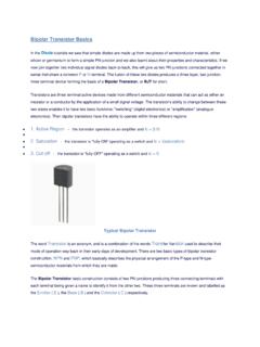
Bipolar Transistor BJT - University of Pittsburgh
sites.pitt.eduBipolar Transistor Basics In the . Diode. tutorials we saw that simple diodes are made up from two pieces of semiconductor material, either silicon or germanium to form a simple PN-junction and we also learnt about their properties and characteristics.
Bias Circuits for RF Amplifiers - QSL.net
www.qsl.netScaling the second transistor allows the current to be multiplied up and used to bias working transistors. • One major drawback to this circuit is that it can inject a lot of noise at the output due primarily to the gain of the transistor Q1 which acts like an amplifier for noise.
Chapter 9: FET Amplifiers And Switching Circuits
staff-old.najah.eduSwitching Circuits 9-1: The Common Source Amplifier (CS Amplifier) FET has an important advantage compared to the BJT due to the FET’s extremely high input impedance. Disadvantages, however, include higher distortion and lower gain. The common-source (CS) amplifier iscomparable to the common-emitter BJT amplifier that you studied in Chapter 6.