Frequency Multipliers - QSL.net
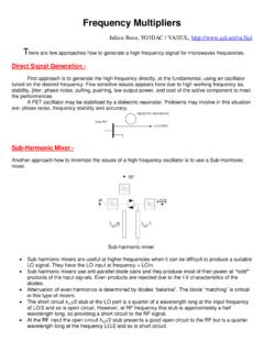
but should not limit the 1 dB gain-compression input voltage. Balanced up-conversion mixer Frequency Multipliers – Another alternative method to generate high frequency signal power with low phase noise is to generate a high-quality lower frequency signal and employ a frequency multiplier to deliver the high
Download Frequency Multipliers - QSL.net

Information
Domain:
Source:
Link to this page:
Documents from same domain
Bias Circuits for RF Devices - QSL.net
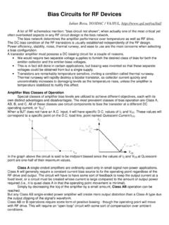
www.qsl.netHighly Stable Active Bias for High Frequency Amplifiers The most common form of biasing in RF circuits is the current mirror. This basic stage is used
Impedance Matching - QSL.net
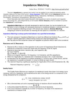
www.qsl.netImpedance Matching Iulian Rosu, YO3DAC / VA3IUL, http://www.qsl.net/va3iul/ The term Impedance is a general term which can be applied to …

Chapter 4 PARABOLIC DISH ANTENNAS - QSL.net
www.qsl.netAperture, Gain, and Efficiency The aperture, gain, and efficiency of an antenna were all defined in Chapter 1 for antennas in general. The aperture A of a dish antenna is the area of the reflector as seen by a
What’s the best antenna? - QSL.net
www.qsl.netWhat’s the best antenna? ... A large beam antenna implies a large tower, rotator, guy cables, concrete, and so forth, and a backyard to put it all in.
CERAMIC FILTER/ CERAMIC DISCRIMINATOR FOR …
www.qsl.net3 This is the PDF file of catalog No.P05E-9. No.P05E9.pdf 00.7.20!MINIMUM ORDER QUANTITY OF CERAMIC FILTER AND DISCRIMINATOR …
Semiconductor IRF512, IRF513
www.qsl.net5-7 irf510, irf511, irf512, irf513 test circuits and waveforms figure 15. unclamped energy test circuit figure 16. unclamped energy waveforms figure 17.
Processing Gain for Direct Sequence Spread TM …
www.qsl.net1 TM AN9633 Processing Gain for Direct Sequence Spread Spectrum Communication Systems and PRISM® Introduction This application note addresses the concept of processing gain (PG) of
Icom IC-746 FAQ - QSL.net
www.qsl.netIC-746 FAQ Recent Changes 2003.02.06 Added another QST article to the article list 2003.02.06 Added current vs voltage chart to power supply section.

Microstrip, Stripline, and CPW Design - QSL.net
www.qsl.netSkin Depth of Planar Conductors At high frequencies, the current flowing in a conductor tends to get confined near the outer surface of the conductor.
Frequency Multipliers - QSL.net
www.qsl.netUp-Conversion Mixer - The third option to generate a high frequency signal is to use an up converter. The design of an up converter has typically received much less attention in terms of design methodology than down converter
Related documents
ABB drives - Technical guide No. 4, Guide to variable ...
library.e.abb.comThis control can be achieved using a frequency converter. As the name suggests, a frequency converter changes the frequency of the alternating current and voltage. A frequency converter con-sists of three parts. Regular 50 Hz 3-phase current is fed in to the rectifier part, which converts it to direct current. The DC voltage
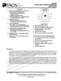
TCS3472 COLOR LIGHT-TO-DIGITAL CONVERTER with IR FILTER
cdn-shop.adafruit.com− Input Voltage Levels Compatible with VDD or 1.8 V Bus Register Set and Pin Compatible with the ... The TCS3472 light-to-digital converter contains a 3 × 4 photodiode array, four analog-to-digital converters ... Clock frequency (I2C only) 0 400 kHz t(BUF) Bus free time between start and stop condition 1.3 μs
SECTION 4 SWITCHED CAPACITOR VOLTAGE CONVERTERS …
www.analog.comconverters which accomplish energy transfer and voltage conversion using capacitors. The two most common switched capacitor voltage converters are the voltage inverter and the voltage doubler circuit shown in Figure 4.1. In the voltage inverter, the charge pump capacitor, C1, is charged to the input voltage during the first half of the ...
Harmonic Distortion from Variable Frequency Drives
ewh.ieee.org• Reactors are rated in %Z for the rated voltage system (i.e. 3%, 5%, 8%, etc.) • Line reactors greater than 5% are not recommended due to voltage drop • Example: A 3% line reactor will cause a 3% voltage drop when passing full rated current 480v*3% = 14.4 volts 480v*5% = 24 volts 480v*8% = 38.4 volts

TPS61088 10-A Fully-Integrated Synchronous Boost …
www.ti.comThe TPS61088 has a wide input voltage range from 2.7 V to 12 V to support applications with single-cell or two-cell Lithium batteries. The device has 10-A switch current capability and is capable of providing an output voltage up to 12.6 V. The TPS61088 uses adaptive constant off-time peak current control topology to regulate the output voltage.