Transcription of Frequency Multipliers - QSL.net
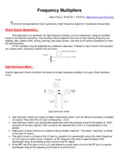
1 Frequency Multipliers Iulian Rosu, YO3 DAC / VA3 IUL, There are few approaches how to generate a high Frequency signal for microwaves frequencies. Direct Signal Generation - First approach is to generate the high Frequency directly, at the fundamental, using an oscillator tuned on the desired Frequency . Few sensitive issues appears here due to high working Frequency as, stability, jitter, phase noise, pulling, pushing, low output power, and cost of the active component to meet the performances. A FET oscillator may be stabilized by a dielectric resonator. Problems may involve in this situation are: phase noise, Frequency stability and accuracy. Sub-Harmonic Mixer - Another approach how to minimize the issues of a high Frequency oscillator is to use a Sub-Harmonic mixer. Sub-harmonic mixer Sub-harmonic mixers are useful at higher frequencies when it can be difficult to produce a suitable LO signal.
2 They have the LO input at Frequency = LO/n. Sub-harmonic mixers use anti-parallel diode pairs and they produce most of their power at odd products of the input signals. Even products are rejected due to the I-V characteristics of the diodes. Attenuation of even harmonics is determined by diodes balance . The diode matching is critical in this type of mixers. The short circuit LO/2 stub at the LO port is a quarter of a wavelength long at the input Frequency of LO/2 and so is open circuit. However, at RF Frequency this stub is approximately a half wavelength long, so providing a short circuit to the RF signal. At the RF input the open circuit LO/2 stub presents a good open circuit to the RF but is a quarter wavelength long at the Frequency LO/2 and so is short circuit. Up-Conversion Mixer - The third option to generate a high Frequency signal is to use an up converter. The design of an up converter has typically received much less attention in terms of design methodology than down converter design, which is common approach in most of the receiver designs.
3 There are some aspects to up converter design which are not relevant to down converters, and vice versa. An up-conversion mixer requires high linearity and low noise to minimize the amount of spurious power spread into adjacent channels. Have to take careful attention at LO amplitude, and LO-to-RF isolation. A good approach for an up-conversion mixer is the balanced mixer which provides good common-mode rejection to suppress LO feed-through and good linearity. The LO level should provide a reasonable compromise between conversion gain and LO power, but should not limit the 1 dB gain-compression input voltage . Balanced up-conversion mixer Frequency Multipliers Another alternative method to generate high Frequency signal power with low phase noise is to generate a high-quality lower Frequency signal and employ a Frequency multiplier to deliver the high Frequency output at the desired Frequency . This approach is the subject of this paper.
4 Frequency Multipliers will always be a way of generating the highest frequencies. A Frequency multiplier has the property that the Frequency of the output signal has an integer multiple of the input Frequency . This approach is commonly adopted in microwave transceivers. Frequency multiplier based microwave transceiver block diagram Even if a multiplier introduces no Phase Noise of its own, the process of Frequency multiplication even by an ideal, noiseless multiplier , inevitably increases the Phase Noise. The reason for this unfortunate characteristic is that a Frequency multiplier is in fact a phase multiplier , so it multiplies the phase deviations as well as the Frequency of the input signal. A square-wave contains odd harmonics. However, by varying the duty cycle of the waveform, so that rectangular-wave results, even order harmonic content can be introduced. The 2nd harmonic content of a rectangular-wave peaks when the duty cycle is 25%, and a 3rd harmonic peaks when duty cycle peaks 16%.
5 The minimum Carrier-to-Noise degradation, CNR, in decibels, caused by an ideal Frequency multiplier is: CNR[dB] = 20*LOG (N) where N is the multiplication factor. Thus, a Frequency doubler (N=2) degrades CNR at the input signal by at least 6dB and a quadrupler (N=4) degrades CNR by at least 12dB. Multiplying a very stable low- Frequency reference signal can still produce signals with better Phase Noise than producing them directly in the microwave Frequency range. For example typical Phase Noise of a 10 MHz Crystal Oscillator is: -170 dBc/Hz @ 100 kHz offset. Using a multiplier chain (10 x 24 = 240) to get a GHz signal, degrades this Phase Noise by 20*LOG(240) = 48 dB, yielding: -170 dBc/Hz + 48 dB = -122 dBc/Hz @ 100 kHz offset. Compare this Phase Noise to a standard LC-tank oscillator working directly at GHz, which has a typical Phase Noise of -100dBc/Hz @ 100 kHz offset. A Frequency multiplier circuit should contain a nonlinear device and filters that enable to select the desired component at the output and separate the source from the generated harmonics.
6 Frequency multiplier Chain with Filters The nonlinear device will produce voltages of higher order from the current of the first harmonic. One of these voltages is of the desired order and will be allowed to exit through the band-pass filter. Low-pass and band-pass filters will present high impedance to all unwanted harmonic voltages. But it turns out that if we allow the currents of the other harmonics to flow, the intermodulation products of those harmonics will contribute to the desired harmonic of the output Frequency . That means we should try to short the currents of the non-desired harmonics. As we want to deliver as much power as possible to the load the Frequency multiplier should be matched at the input (for the input Frequency ) and at the output (for the output Frequency ). A signal of pure sine waves contains only its fundamental Frequency . Any departure from this sine-wave pattern, no matter how small, is due to the presence of additional frequencies that are multiples (harmonics) of the fundamental Frequency .
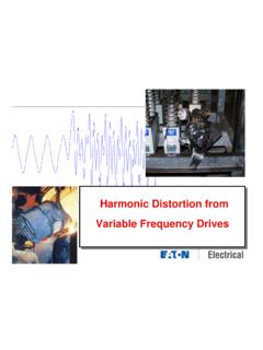
7 If this non-sinusoidal wave can be given an exact mathematical description, the amplitude and phase of each harmonic Frequency it contains may be calculated. For example an amplifier that is driven slightly beyond the cutoff point will slice off the tip of the loop. Negative clipping of the sine-wave (1/8 of the period) An analysis will show that this deformation of the sine-wave gives rise to an endless number of harmonics, with amplitudes that tend to decrease (not uniform) with increase of Frequency . If an amplifier is driven into cutoff for a third of the duration of a period, in this case harmonic content is maximum for every harmonic divisible by three. Peculiarly, the two intervening harmonics have amplitudes of equal magnitude. Negative clipping of the sine-wave (1/3 of the period) In case where the lower excursion of the sine wave has been clipped off entirely, (as a rectified half wave), every harmonic with an uneven number has disappeared.
8 The fundamental Frequency has an amplitude equal to the actual amplitude of the half wave. Negative clipping of the sine-wave (1/2 of the period) Next case shows a sine wave sliced off even more, so that only a third of the period is left. The envelope over the harmonic columns shows a pattern much like situation above, but the fundamental Frequency has lower amplitude and higher harmonics, so have larger amplitudes than those of situation above. Negative clipping of the sine-wave (2/3 of the period) If the sine-wave is sliced off so much that only one-sixth of the period remains, the fundamental Frequency has an amplitude of only 43% of the curve but the harmonics are quite prominent. In the plot below the harmonic amplitude shows a wave pattern with minima at the 9th, 15th, 21st and 27th harmonic. Negative clipping of the sine-wave (5/6 of the period) Looking to the all above plots we can see that we get the maximum 2nd harmonic level when slicing off two-thirds of the sine-wave which would give better 2nd harmonic performance than any of the other clipped waveforms pictured.
9 Thus, for the highest 2nd harmonic content, 66% of the sine-wave (2/3 of the period) must be clipped off. This represents a conduction angle of about 119 which provides a 2nd harmonic amplitude of 55% of the basic curve's amplitude. If Frequency tripling is wished (higher 3rd harmonic), the horizontal part of the curve (that is, the duration of the cutoff) should be in the neighborhood of three-quarters of the total period. To obtain higher order Frequency multiplication we can cascade several Multipliers . This can increase conversion efficiency but also increases complexity. There are different possibilities concerning the nonlinear device: We need a device with a nonlinear characteristic in order to produce higher order harmonics. The nonlinear characteristic might be a nonlinear I-V or C-V relationship. Usually wideband Multipliers use a nonlinear I-V characteristic, but when we want to design a Frequency multiplier with high efficiency, and not high bandwidth, we prefer the nonlinear C-V characteristic.
10 For example a varactor diode has a nonlinear C-V characteristic. Frequency Multipliers Waveforms Any non-sinewave repetitive waveform contains energy at harmonics of the fundamental Frequency . The task is to create a non-linear circuit that produces a waveform with significant signal strength at the desired harmonics. Figure below shows the amplitude terms (peak value of the nth harmonic sine wave) for various waveforms. Harmonic amplitude terms for various waveforms (C. Wenzel) Can be seen that waveforms with fast edges have larger high Frequency harmonics. Harmonics without vertical edges have n2 in the denominator, but the waveforms with fast edges only have n in the denominator. The timing (duty-cycle) between the positive and negative edges of a pulse determines which harmonics are emphasized. For example, a 50% duty-cycle square-wave has only odd harmonics. In this situation the timing is wrong for the buildup of even-harmonic energy, but a 25% duty-cycle contains large even harmonics: the edges occur at the right time to reinforce certain even harmonics.