
HSPICE User Guide: Simulation and Analysis
HSPICE® User Guide: Simulation and Analysis Version B-2008.09, September 2008
Download HSPICE User Guide: Simulation and Analysis

Information
Domain:
Source:
Link to this page:
Documents from same domain
Diodes and Transistors
inst.eecs.berkeley.eduDiodes and Transistors 1. ... basic semiconductor physics. We won’t discuss the details because the point of this ... switch. Below the specified ...
HSPICE Tutorial - University of California, Berkeley
inst.eecs.berkeley.eduHSPICE Tutorial Contents 1 Introduction 1 ... ee105 spice tutorial example 1 - simple rc circuit in the Results Browser and double-clicking vs and vo to plot them in the graph. You may have been able to guess from the netlist, but you’ll see that vsis a …
Introduction to LabVIEW - University of California, …
inst.eecs.berkeley.eduIntroduction to LabVIEW 1. Introduction Welcome to the LabVIEW component of EE100! This lab is just a simple introduction to the graphical circuit simulation ...
Introduction to LabVIEW For Use in Embedded …
inst.eecs.berkeley.eduUC Berkeley EE249 Hugo.Andrade@ni.com Introduction to LabVIEW For Use in Embedded System Development
EE105 –Fall 2015 Microelectronic Devices and Circuits
inst.eecs.berkeley.eduSummary of MOS Single-Transistor Amplifiers MOS Common Source Common Source with Deg. Common Drain Common Gate Ri ∞ ∞ ∞ Small Ro Large Very Large Small Large
Introduction to Digital Systems - University of …
inst.eecs.berkeley.eduDepartment of EECS EE100/42-43 Spring 2007 Rev. 1 Introduction to Digital Systems 0. Acknowledgments Many thanks to Prof. Bernhard Boser and National Instruments for funding this project in the
EE126: Probability and Random Processes - Lecture 1 ...
inst.eecs.berkeley.eduprobability 4 The probabilities summed over all of the base outcomes always equals 1 Example: Toss a fair coin twice 1 Base outcomes are HH,HT,TH,TT 2 This covers all the possibilities. M.E. 3 Each of these outcomes is equally likely 4 Assign each outcome a probability of 0:25. The list (set) of base outcomes is called the Sample Space.
EECS 126 Probability and Random Processes: Course Syllabus ...
inst.eecs.berkeley.eduDescription: Probability is a mathematical discipline that allows one to reason about uncertainty: it helps us to predict uncertain events, to make better decisions under uncertainty, and to design and build systems. Throughout the course, we will teach you the fundamental ideas of probability and random processes along with the labs.

3-Phase Brushless DC Motor Pre-Driver
inst.eecs.berkeley.eduDescription The A4931 is a complete 3-phase brushless DC motor pre-driver . The device is capable of driving a wide range of N-channel power MOSFETs and can support motor supply voltages up to
DS -V I G - EECS Instructional Support Group Home Page
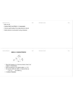
inst.eecs.berkeley.eduG D S I D I G-V DS + + V G S _ NMOS I-V CHARACTERISTIC • Since the transistor is a 3-terminal device, there is no single I-V characteristic. • Note that because of the gate insulator, I G = 0 A. • We typically define the MOS I-V characteristic as I D vs. V DS for a fixed V GS. • 3 modes of operation
Related documents

Pspice Tutorial
www.hkn.umn.eduVariable Resistor R_var Analog ... To simulate a short circuit place a small resistor across node A and node B. For this example I used a 1 femto ohm. You should get Isc = 1.765mA for a short circuit current. For Voc replace the value with a large value, for this example I use

Chapter 14 BJT Models - University of Washington
class.ece.uw.eduFor both the vertical and lateral the resistor model parameters, RB, RBM, RE, and RC are scaled by the following equation. where R is either RB, RBM, RE, or RC. BJT Current Convention The direction of current flow through the BJT is assumed for example purposes in Figure 13-1. Use either I(Q1) or I1(Q1) syntax to print the collector current.

How to Simulate a Variable Resistor in LTSpice
eecs.oregonstate.eduof resistor that you want to be variable, to be {R} • Click on .op (far right on the toolbar) • Type: .step param R 1 10k 1k (steps from 1 to 10K in 1k increments) o. You will need to fill in the correct values, based on the resistive sensor you used • Click Simulate -> Run -> Go to the DCop pnt tab …

Laboratory 2: Voltage and current dividers, Wheatstone ...
faculty.ontariotechu.ca2. Using the same circuit in Figure 2-1, add a load resistor RL in parallel to R2 and use the values V1 of 10 V, R1 and R2 both of 2 k Ω and RL of 1 kΩ, 2 kΩ, 3.3 kΩ, 4.7 kΩ, 5.6 kΩ, and 10 kΩ: 2.1. Simulate this loaded voltage divider circuit in OrCad/PSpice and measure the output voltage for each value of RL.

DC motor circuits
static.sparkfun.comArduino cannot supply variable DC output! Arduino lacks a true analog output! Use Pulse-width modulation (PWM) to simulate a variable DC supply voltage! PWM is a common technique for supplying variable power levels to “slow” electrical devices such as …

pspice tutorial transient
www.csun.eduFor this part we will simulate the circuit as shown in figure 1. Open a new PSPICE project ... This time a display window will open and a graph of the resistor voltage will appear. Of course, since this is a DC circuit, all we see is a straight line, or constant voltage. ... plotting a graph with time as the x-axis variable. Later in the course ...

NI myRIO Project Essentials Guide
www.ni.comcurrent-limiting resistor; you may instead use two series-connected 100 resistors or two parallel-connected 470 ... Blink two adjacent LEDs to simulate a railroad crossingsignal. 3. Blink the green and blue LEDs of the RGB ... DISCRETELED 4. Create an LED variable-intensity dimmer with the PWM Express VI to create a pulse-width ...

Application of LTSpice Modeling to Vishay Temperature Sensors
www.vishay.comThe first run will simulate the nominal case; the remaining runs will simulate a Gaussian normal distribution around the nomina l with a standard deviation of a fourth of the tolerance. We have applied this modification to the TFPT (cf point 5.1). In the netlist of the TFPT model, the function MC(x, tolx) must be replaced by MCG(x,tolx).