
Instrument Transformer Basic Technical Information and ...
The ratio of an instrument transformer is the relationship of its primary rating to its secondary rating. For example, the potential transformer mentioned above having a rating of 480:120 volts will have a ratio of 4:1 and the current transformer having a rating of 400:5 amperes will have a ratio of 80:1. Magnetic Circuits Rating and Ratio
Download Instrument Transformer Basic Technical Information and ...

Information
Domain:
Source:
Link to this page:
Documents from same domain

DIGITAL CONTROL SYSTEM PRODUCT SOLUTIONS …
www.gegridsolutions.comUnlock the value of your substation data with Alstom™s multi-function substation server DIGITAL CONTROL SYSTEM PRODUCT SOLUTIONS DAPserver Multi-function substation server
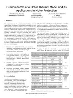
Fundamentals of a Motor Thermal Model and its …
www.gegridsolutions.comMotor Thermal Model Protection Applications 41 1. Abstract This paper discusses the fundamentals of a motor thermal model and its mathematical interpretation and physics for the
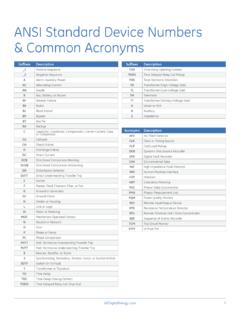
ANSI Standard Device Numbers & Common …
www.gegridsolutions.comGEDigitalEnergycom 1 ANSI Standard Device Numbers & Common Acronyms Suffixes Description _1 Positive-Sequence _2 Negative-Sequence A Alarm, Auxiliary Power AC Alternating Current ...

Instrument Transformer Basic Technical …
www.gegridsolutions.comg ITI Digital Energy Instrument Transformer Basic Technical Information and Application

MiCOM P543, P544, P545, P546 - GE Grid Solutions
www.gegridsolutions.comMiCOM P543, P544, P545, P546 Technical Manual Current Differential Relays Platform Hardware Version: K Platform Software Version: …
NERC Critical Infrastructure Protection: Cyber Asset ...
www.gegridsolutions.comNERC Critical Infrastructure Protection: Cyber Asset Protection. 7. 1. Introduction. The NERC Critical Infrastructure Protection Committee (CIPC)

469 Motor Management Relay - GE Grid Solutions
www.gegridsolutions.comtoc table of contents 469 motor management relay – instruction manual toc–i table of contents 1: getting started important procedures ..... 1-1
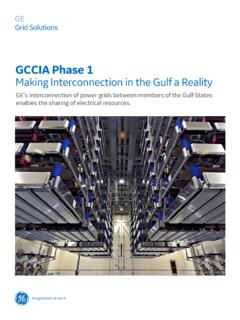
GCCIA Phase 1 - GE Grid Solutions
www.gegridsolutions.comThe GCCIA is an organisation formed in July 2001 in order to create an integrated and sustainable energy economy amongst the six Gulf States. MakinG interconnection in the Gulf a reality GCCIA Phase 1
Transmission Line Protection Principles - GE Grid …
www.gegridsolutions.comTransmission Line Protection Principles 7 1. Introduction Transmission lines are a vital part of the electrical distribution system, as they provide the …
Transformer Protection Principles - GE Grid Solutions
www.gegridsolutions.comTransformer Protection Principles 47 phase shift of the protected transformer. Traditional installations may use delta-connected or wye-connected CTs that externally
Related documents
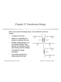
Chapter 15 Transformer Design - University of Colorado …
ecee.colorado.eduFundamentals of Power Electronics Chapter 15: Transformer design11 15.2 Step-by-step transformer design procedure The following quantities are specified, using the units noted: Wire effective resistivity ( -cm) Total rms winding current, ref to pri Itot (A) Desired turns ratios n2/n1, n3/n1, etc. Applied pri volt-sec 1 (V-sec)

Calculation of the Current Transformer Accuracy Limit Factor
library.e.abb.comCalculation of the Current Transformer 1MRS 755481 Accuracy Limit Factor 1. Scope This document describes the calculation of the actual accuracy limit factor (F a) for protection-type (P) current transformers (CT). First, the calculation of the actual burden of the CT, including connection wires and protection relay impedance, is presented.

Littelfuse Transformer Protection White Paper
m.littelfuse.comtime-delay fuses may be rated at 125% of transformer secondary current. 2. Where the required fuse rating does not correspond to a standard fuse rating, the next higher standard rating is permitted. 3. An individual primary fuse is not required if the primary circuit fuse is not greater than 300% of transformer primary current. Table 2:

Chapter 5
pages.mtu.edu1. With no load on the transformer measure: the RMS current into the transformer the input voltage the real power into transformer 2. The product of the voltage and the current gives the apparent power, S. 3. Science the real power is known, we can find the power factor and the impedance angle. The elements then can be calculated. 16
Power Transformer Factory Test using IEEE Standards
r5.ieee.orgPower transformer testing Power Transformer Factory Test using IEEE Standards Waldemar Ziomek ... Failure detection is by comparison of voltage and current wave shapes at reduced level and full level or between 2 wave shapes at the same level in case of non-linear resistors 30
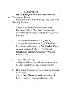
LECTURE 34 HIGH FREQUENCY TRANSFORMER - Walter …
www.engr.colostate.eduripple and input ripple current, and is an important concept in control loop design. In a single-ended power circuit such as the forward converter, the power switch, the transformer, and the output rectifier all operate at the switching frequency and there is no confusion. The transformer frequency and the switching frequency are the same. This is