
Series and parallel combinations
EE 201 series/parallel combinations – 12 Breaking down networks using series and parallel R 3 R 4 R 5 R eq R 2 But not all circuits are simple R 1 combinations of series or parallel resistors. The initial example circuit clearly has some things that are in series and some elements that have a parallel-type connection.
Download Series and parallel combinations

Information
Domain:
Source:
Link to this page:
Documents from same domain
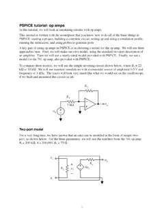
pspice op amp - Iowa State University
tuttle.merc.iastate.eduThis tutorial is written with the assumption that you know how to do ... So it looks like the uA741 model has the potential to be a reasonably accurate PSPICE op amp

How Millennials Can Get Rich Slowly
tuttle.merc.iastate.eduHow Millennials Can Get Rich Slowly William J. Bernstein ©2014 . Would you believe me if I told you that there’s an investment strategy that a seven-year-old could ... and vigor, your retirement options may well range between moving in with your kids and sleeping under a bridge in the rain.
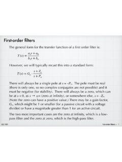
First-order filters - Iowa State University
tuttle.merc.iastate.eduFirst-order filters The general form for the transfer function of a first order filter is: T(s) = G o ... Use the standard definition for cut-off frequency, which is the frequency at which the magnitude is down by from the value in the pass-band. For our low-pass function, the pass band is at low frequencies, and the ...

Basic PMOS structure - Iowa State University
tuttle.merc.iastate.eduohmic or linear v GS < V T v DS < v GS – V T i D = K[v GS – V T]2 saturation Summary of PMOS equations K = 1 2 μCox W L VT < 0 Note the equations are identical to the NMOS equations. For a PMOS, v GS and v DS are both negative and the current flows from source to drain.
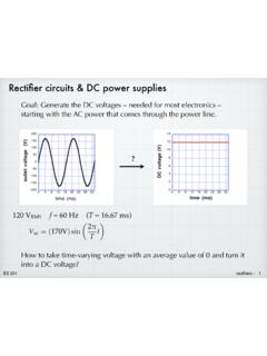
Rectifier circuits & DC power supplies
tuttle.merc.iastate.eduNov 01, 2015 · Rectifier circuits & DC power supplies Goal: Generate the DC voltages – needed for most electronics – starting with the AC power that comes through the power line.? 120 V RMS 9DF=( 9)sin 7 W f = 60 Hz (T = 16.67 ms) How to take time-varying voltage with an average value of 0 and turn it into a DC voltage?
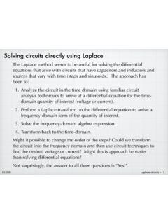
Solving circuits directly using Laplace
tuttle.merc.iastate.eduAnalyze the circuit in the time domain using familiar circuit analysis techniques to arrive at a differential equation for the time-domain quantity of interest (voltage or current). 2. Perform a Laplace transform on the differential equation to arrive a ... C in the RLC circuit below. The input is a step function, v i ...
Thevenin equivalent circuits - Iowa State University
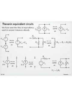
tuttle.merc.iastate.eduJun 10, 2014 · The open-circuit voltage / short-circuit current approach can be used to calculate the Thevenin equivalent for a known circuit. Consider the circuit from slide 4: + – V S R 1 R 2 I S 9V 6 mA 1.5 k! 3 k! Open-circuit voltage – Use whatever method you prefer. We’ll use node voltage in this case. + – V S R 1 R 2 I S v a + – v oc YRF= YD ...
superposition - Iowa State University
tuttle.merc.iastate.eduEE 201 superposition – 2 2va + 6vb = 2V 8va 2vb = 36V Solving gives: v a = 5 V, v b = 2 V 8v a 2v b = 0 2v a + 6v b = 2V Solving gives: and 2v a + 6v b = 0 8v a 2v b = 36V A math problem: Mathematically, we can solve the simultaneous equations a piece at a
npn Bipolar Junction Transistor - Iowa State University
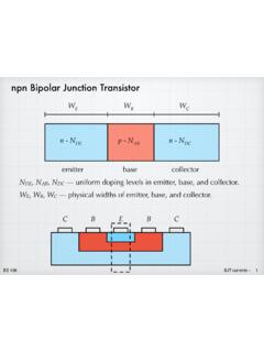
tuttle.merc.iastate.edujunction — very surprising! EE 436 BJT currents – 6 The electron current in the base is determined by the boundary ... External (terminal) currents. All currents depend on V BE in exactly the same way. Although it is a messy exponential, they …

Diffusion of dopants in silicon - Iowa State University
tuttle.merc.iastate.eduSolid-solubility limit In principle, the surface concentration that shows up in the diffusion expression could be controlled by changing the flow of a gaseous source of the dopant. (More about this later.) In practice, however, N s will be determined by the “solid solubility limit” of the dopant in the silicon. This is the thermodynamic ...
Related documents
RLC Resonant Circuits - University of Cambridge
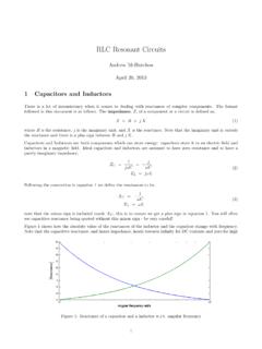
mlg.eng.cam.ac.ukTherefore, for series circuits it is in general simpler to calculate the max energy stored by considering the inductor and in parallel circuits by considering the capacitor. Real power is only dissipated in the resistors, P= V Rrms I Rrms = I 2 rms R= V2 Rrms R (16) For the series RLC circuit it is easiest to consider currents, Q(s)! 0 = ! 0 I2 ...
Experiment 4 ~ Resistors in Series & Parallel
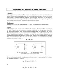
www.umsl.eduExperiment 4 ~ Resistors in Series & Parallel Objective: In this experiment you will set up three circuits: one with resistors in series, one with resistors in parallel, and one with some of each. You will be building circuits similar to the ones you will be working with in homework and exam problems. This experiment should show you the difference
Chapter 21: RLC Circuits
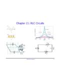
www.phys.ufl.eduPHY2054: Chapter 21 19 Power in AC Circuits ÎPower formula ÎRewrite using Îcosφis the “power factor” To maximize power delivered to circuit ⇒make φclose to zero Max power delivered to load happens at resonance E.g., too much inductive reactance (X L) can be cancelled by increasing X C (e.g., circuits with large motors) 2 P ave rms=IR rms ave rms rms rms cos
Physics 215 - Experiment 11 Series and Parallel Circuits
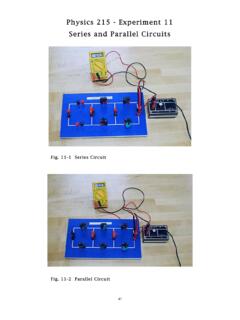
www.phy.olemiss.eduSeries and Parallel Circuits 44 + V - 2 The third type of circuit you will construct is a ccombination circuit (Fig. 11-3 and Fig. 11-6). Resistive elements are not connected in series or parallel. To analyze this type of circuit, it should first be simplified (reduced to an equivalent
`Ohm’s Law III -- Resistors in Series and Parallel
www.phys.utk.eduseries resistance. Wires have resistance that depend on wire size, length, and type of material. Wires add series resistance to circuits, just as good and bad connections add also. In order to fully understand electrical circuits and their behavior, one must first understand Ohm’s Law and the principles regarding resistors in series and parallel
Series and Parallel Circuits - Electronics
cie-wc.eduSeries-Parallel Circuits • Series-Parallel circuits can be more complex as in this case: In circuit (a) we have our original complex circuit. In circuit (b) we have resistors R 1 and R 2 combined to get 13.2Ω. R 4 is in series with the newly combined R 12 and their added value is 51.2Ω. And now (c) we are left with R 124 in parallel with R 3.
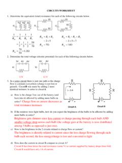
Circuit A Circuit B
www.livingston.orgCIRCUITS WORKSHEET 1. Determine the equivalent (total) resistance for each of the following circuits below. : 2. Determine the total voltage (electric potential) for each of the following circuits below. 13V 12 V 3. In a series circuit there is just one path so the charge flow is constant everywhere (charge is not lost or gained).
Chapter 8 Natural and Step Responses of RLC Circuits
www.ee.nthu.edu.twSeries . RLC . Circuit. 2 Key points What do the response curves of over-, under-, and critically-damped circuits look like? How to choose R, L, C values to achieve fast switching or to prevent overshooting damage? ...

Series -Parallel Circuits - Oakton Community College
www.oakton.eduOverview of Series-Parallel Circuits A series-parallel circuit, or combination circuit, combines both series and parallel connections. Most electronic circuits fall into this category. Series-parallel circuits are typically used when different voltage and current values are required from the same voltage source. Series components form a series ...
Experiment #1: RC Circuits
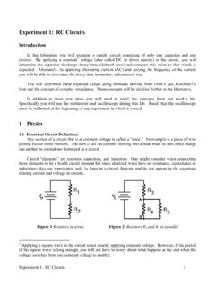
courses.physics.ucsd.eduIn more complicated circuits you will need to generalize the notions of series and parallel. For example, in Figure 2, the equivalent resistance of R 4 and R 5 in parallel, 1 R 4 1 R 5 1 R 4 * R 5 R 4 R 5 , is in series with R 3. 1.2 Ohm’s Law Ohm’s Law states that for a resistor the current and voltage are in phase and proportional. That ...