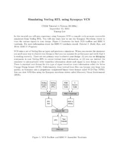
Simulating Verilog RTL using Synopsys VCS
Sep 12, 2010 · Verilog allows a designer to specify how the abstract delay units in their design map into real time units using the ‘timescale compiler directive. To make it easy to change this parameter you will specify it on the command line instead of in the Verilog source. +vc+list -CC
Download Simulating Verilog RTL using Synopsys VCS

Information
Domain:
Source:
Link to this page:
Documents from same domain
Diodes and Transistors
inst.eecs.berkeley.eduDiodes and Transistors 1. ... basic semiconductor physics. We won’t discuss the details because the point of this ... switch. Below the specified ...
HSPICE Tutorial - University of California, Berkeley
inst.eecs.berkeley.eduHSPICE Tutorial Contents 1 Introduction 1 ... ee105 spice tutorial example 1 - simple rc circuit in the Results Browser and double-clicking vs and vo to plot them in the graph. You may have been able to guess from the netlist, but you’ll see that vsis a …
Introduction to LabVIEW - University of California, …
inst.eecs.berkeley.eduIntroduction to LabVIEW 1. Introduction Welcome to the LabVIEW component of EE100! This lab is just a simple introduction to the graphical circuit simulation ...
Introduction to LabVIEW For Use in Embedded …
inst.eecs.berkeley.eduUC Berkeley EE249 Hugo.Andrade@ni.com Introduction to LabVIEW For Use in Embedded System Development
EE105 –Fall 2015 Microelectronic Devices and Circuits
inst.eecs.berkeley.eduSummary of MOS Single-Transistor Amplifiers MOS Common Source Common Source with Deg. Common Drain Common Gate Ri ∞ ∞ ∞ Small Ro Large Very Large Small Large
Introduction to Digital Systems - University of …
inst.eecs.berkeley.eduDepartment of EECS EE100/42-43 Spring 2007 Rev. 1 Introduction to Digital Systems 0. Acknowledgments Many thanks to Prof. Bernhard Boser and National Instruments for funding this project in the
EE126: Probability and Random Processes - Lecture 1 ...
inst.eecs.berkeley.eduprobability 4 The probabilities summed over all of the base outcomes always equals 1 Example: Toss a fair coin twice 1 Base outcomes are HH,HT,TH,TT 2 This covers all the possibilities. M.E. 3 Each of these outcomes is equally likely 4 Assign each outcome a probability of 0:25. The list (set) of base outcomes is called the Sample Space.
EECS 126 Probability and Random Processes: Course Syllabus ...
inst.eecs.berkeley.eduDescription: Probability is a mathematical discipline that allows one to reason about uncertainty: it helps us to predict uncertain events, to make better decisions under uncertainty, and to design and build systems. Throughout the course, we will teach you the fundamental ideas of probability and random processes along with the labs.
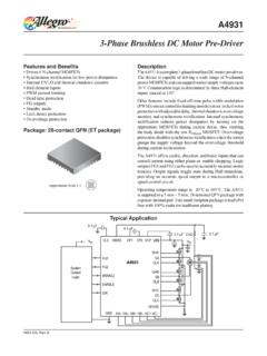
3-Phase Brushless DC Motor Pre-Driver
inst.eecs.berkeley.eduDescription The A4931 is a complete 3-phase brushless DC motor pre-driver . The device is capable of driving a wide range of N-channel power MOSFETs and can support motor supply voltages up to
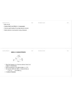
DS -V I G - EECS Instructional Support Group Home Page
inst.eecs.berkeley.eduG D S I D I G-V DS + + V G S _ NMOS I-V CHARACTERISTIC • Since the transistor is a 3-terminal device, there is no single I-V characteristic. • Note that because of the gate insulator, I G = 0 A. • We typically define the MOS I-V characteristic as I D vs. V DS for a fixed V GS. • 3 modes of operation
Related documents

Verilog-A and Verilog-AMS Reference Manual
edadownload.software.keysight.comAdvanced Design System 2011.01 - Verilog-A and Verilog-AMS Reference Manual 5 Errata The ADS product may contain references to "HP" or "HPEESOF" such as in file names and directory names. The business entity formerly known as "HP EEsof" is now part of Agilent Technologies and is known as "Agilent EEsof". To avoid broken functionality and
Icarus Verilog + GTKWave Guide
inf-server.inf.uth.grIcarus Verilog About Icarus Verilog is a free Verilog simulation and synthesis tool. It compiles source code written in Verilog (IEEE-1364) into some target format. It also generates netlists for the synthesis part. It's by far the best free tool and many people work on that making it more and more complete day by day.
Correct Methods For Adding Delays To Verilog Behavioral …
sunburst-design.comMar 07, 2001 · Rev 1.1 To Verilog Behavioral Models 3.0 Blocking assignment delay models Adding delays to the left-hand-side (LHS) or right-hand-side (RHS) of blocking assignments (as shown in Figure 1) to model combinational logic is very common among new and even experienced Verilog users, but the practice is flawed. For the adder_t1 example shown in …

Finite State Machines - MIT - Massachusetts Institute of ...
web.mit.eduWrite Verilog module(s) for FSM 6.111 Fall 2017 Lecture 6 14. Step 1A: Block Diagram fsm_clock reset b0_in b1_in lock button button button Clock generator Button Enter Button 0 Button 1 fsm state unlock reset b0 b1 LED DISPLAY Unlock LED 6.111 Fall 2017 Lecture 6 15. Step 1B: State transition diagram RESET

A Verilog HDL Test Bench Primer - Cornell University
people.ece.cornell.eduthe Verilog code for each of the individual modules is compiled and the simulation is run. By applying stimulus and simulating the design, the designer can be sure the correct functionality of the design is achieved. This design uses a loadable 4-bit counter and test

Verilog - Operators
web.engr.oregonstate.eduVerilog - Operators Arithmetic Operators (cont.) I Unary operators I Operators "+" and "-" can act as unary operators I They indicate the sign of an operand i.e., -4 // negative four +5 // positive five!!! Negative numbers are represented as 2’s compliment numbers !!!!! Use negative numbers only as type integer or real !!!

Summary of Verilog Syntax
www.iitg.ac.inVerilog has special syntax restriction on using both reduction and bitwise operators within the same expression — even though reduction operator has higher precedence, parentheses must be used to avoid confusion with a logical operator.