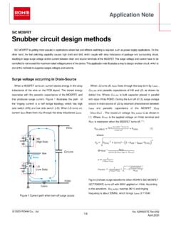
Snubber circuit design methods - Rohm
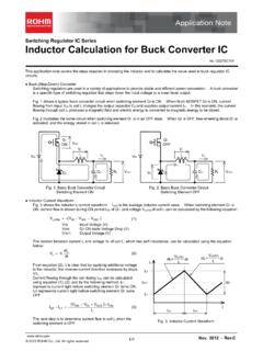
can be increased, and therefore, the clamping effectiveness. C SNB and R SNB are determined by equation (2) and (3) respectively. Power consumption of R SNB is determined by following equation (6) which does not have the second term of equation (4) including C SNB and f sw. This leads efficient clamping capability and makes higher frequency of f sw
Download Snubber circuit design methods - Rohm

Information
Domain:
Source:
Link to this page:
Documents from same domain
SiC Power Devices and Modues Application Note
fscdn.rohm.com600V 400V 100V Si C D D D D G2GG 3ÿ G2GG H 9×3ÿ FÜ SiFÜ 8 æ GG ö G ì e Majority carrier device : High speed Minority carrier device : Low on-resistance, but low speed ・ Significant reduction in recovery loss ・ Downsizing of devices by increase in frequency Can be manufactured in this area, but little advantage over Si
Linear Regulator IC Series Linear Regulator 기초
fscdn.rohm.comLinear Regulator 는 기본적으로 입력, 출력, GND 핀으로 구성되며, 출력이 가변일 경우는 출력전압의 귀환이 필요 하기 때문에 귀환(Feedback)핀이 추가됩니다. (Figure 1) IN OUT FB GND V IN V O Figure 1. Linear Regulator 의 기본구성 Linear Regulator 내부회로의 개요는 Figure 2 …
Op-Amp/Comparator Application Note - Rohm
fscdn.rohm.comop-amp. Generally, an op-amp is composed of three stages: the input stage, the gain stage, and the output stage. The input stage is configured with a differential amplification stage that amplifies the differential voltage between the two terminals. In addition, it does not amplify the common-mode signal component (a condition where no ...
Efficiency of Buck Converter
fscdn.rohm.comEfficiency of Buck Converter Switching regulators are known as being highly efficient power sources. To further improve their efficiency, it is helpful to understand the basic mechanism of power loss. This application note explains power loss factors and methods for calculating them.
Snubber Circuit for Buck Converter IC : Power Management
fscdn.rohm.comSnubber Circuit for Buck Converter IC AEK59-D1-0311-0 For example, when the input voltage VIN is 24 V and the switching frequency fSW is 1 MHz, 2 Ë Ì Ç » L680 pF H24 6 H1 MHz L0.39 W the generated consumption power of 0.39 W requires a 6432 size resistor (2512 in inches) with a rated power of 1 W.
ISO 26262: Functional Safety Standard for Modern Road …
fscdn.rohm.comIntrinsic safety is a method for ensuring safety by removing the causes of danger. Functional safety, on the other hand, is a method of reducing risks to an acceptable level to ensure safety ... verification, prototyping, and evaluation are clarified, with reviews performed at each stage. It is also necessary to manage the documents created at
Calculation of Power Loss (Synchronous) : Power Management
fscdn.rohm.comCalculation of Power Loss (Synchronous) This application note describes how to obtain the power loss required to calculate the temperature of a semiconductor device. Temperature control is important to ensuring product reliability. Figure 1 is a circuit diagram of a synchronous rectification type DC/DC converter. Figure 2 shows a switching node ...
Inductor Calculation for Buck Converter IC
fscdn.rohm.comInductor Calculation of Buck Converter Current-difference between max. and min. (ILP-ILT) is as follows: IN SW D SW IN SW OUT D OUT LP LT V V V L f V V V V V I I (15) Equations (13) and (15) show that large inductance L and high switching frequency will reduce maximum current (ILP)and current difference between max. and min. (ILP-ILT).
Hysteresis Setting for Comparator - Rohm
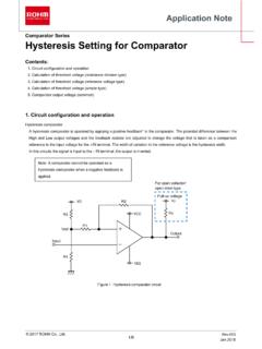
fscdn.rohm.comprovided only to illustrate the standard usage and operations of the Products. The peripheral conditions must be taken into account when designing circuits for mass production. The technical information specified herein is intended only to show the typical functions of and examples of application circuits for the Products.

ROHM Switching Regulator Solutions Synchronous Buck ...
fscdn.rohm.comROHM Switching Regulator Solutions Synchronous Buck Converter Controller BD9611MUV-EVK-001 Description Using a synchronous rectified step-down DC/DC converter IC BD9611MUV BD 9611MUV-EVK-001 evaluation board 15.0 V ~ output a 24 V input voltage 12.0 V. Provides 10.0A output current. Output current is possible with current settings by selecting
Related documents
Pneumatic Symbols - Norgren
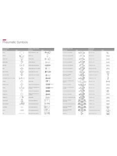
cdn.norgren.comAuto drain valve Cylinder, clamping Booster regulator Cylinder, double acting Check valve Cylinder, double acting, dual stroke Cooler Cylinder, double acting, with air cushion Digital flow switch Cylinder, double acting, with lock Filter with auto drain Cylinder, double acting, with magnet Filter-Regulator-Lubricator with auto drain Cylinder ...
EEE-INST-002: Instructions for EEE Parts Selection ...
nepp.nasa.govthat do not utilize a military style hood “clamping” mechanism to support female contact engagement tines. c. Connectors with compliant pin “press fit” terminations to flight boards. d. MIL-DTL-55302/ 131 through 134 Eurocard type PWB connectors e. MIL-DTL-55302/ 157 & 158 VME type PWB connectors f.

High-speed CAN transceiver - NXP
www.nxp.comBus dominant clamping diagnosis Cold start diagnosis (first battery connection) 3. Quick reference data Table 1. Quick reference data Symbol Parameter Conditions Min Typ Max Unit VCC supply voltage 4.5 - 5.5 V VIO supply voltage on pin VIO 2.8 - 5.5 V Vuvd(VCC) undervoltage detection voltage on pin VCC 33.54.3V Vuvd(VIO) undervoltage detection ...

PESD2CAN CAN bus ESD protection diode
assets.nexperia.comLow clamping voltage: VCL =41V a tI PP =5A Ultra low leakage current: IRM <1nA ESD protection up to 30 kV IEC 61000-4-2, level 4 (ESD) IEC 61000-4-5 (surge); IPP =5A at t p =8/20 s AEC-Q101 qualified 1.3 Applications CAN bus protection Automotive applications 1.4 Quick reference data Table 1. Quick reference data 2.
Sensorless BLDC motor control and BEMF sampling …
www.st.comThe current in the clamping diode should not exceed 5mA and should typically be around 2mA. For a high voltage (400V) DC bus, 200k resistors are to be used. For safety and power dissi-pation, two 100k resistors in serial are implemented on each phase. Resistors implemented on the starter kit board are two 82k which is suitable both for the 24V

ULN2001, ULN2002 ULN2003, ULN2004 - STMicroelectronics
www.st.comIF Clamping diode continuous current 350 mA VR Clamping diode reverse voltage 50 V TA Operating ambient temperature range - 40 to 85 °C TSTG Storage temperature range - 55 to 150 °C TJ Junction temperature 150 °C ESD Electrostatic discharge rating - HBM 2 kV Table 2. Thermal data Symbol Parameter DIP-16 SO-16 TSSOP16 Unit

TUNE GUITAR TO PITCH BEFORE TAKING MEASUREMENTS.
www.martinguitar.coming bolts to 25 inch-lb of torque. Tighten the lower clamping bolt first (accessible through the middle of the decorative grommet on the back), then the upper bolt (the head of which is exposed and visible in the block of the instrument) Intonation Adjustment To make adjustments: 1. Detune the guitar approximately 2 full steps 2.

Our work on motor finance – final findings
www.fca.org.uk3 Section 1 Financial Conduct Authority Our work on motor finance – final findings. 1 Introduction. 1.1 In April 2017, we announced in our Business Plan for 2017/18 a review of the motor finance sector.

HOW TO
images.thdstatic.comCLAMPING TOOL A clamping square will help to align the tops and sides of the towers at a 90 degree angle. This will help to ensure the tower is square. TAPE MEASURE Measure the diagonal length from corner to corner. This length should equal the measurement of the opposite corners. This will help to ensure the tower is square.